Once a good television antenna was a deficit, buying quality and durability, to put it mildly, did not differ. Make an antenna for the "box" or "coffin" (old lamp TV) with their own hands was considered an indicator of skill. Interest in improvised antennas does not fuss in our day. There is nothing strange here: the conditions for receiving TV changed dramatically, and manufacturers believing that there is nothing significant in the theory of antennas and will not, most often adapt to the long-known designs of electronics, without thinking about the fact that The main thing for any antenna is its interaction with the signal on the air.
What has changed on the air?
Firstly, Almost the entire volume of TV broadcasting is currently carried out in the DMW range. First of all, from economic considerations, the antenna-feeder economy of transmitting stations is much simplified in it, and, more importantly, the need for its regular maintenance by highly qualified specialists engaged in heavy, harmful and dangerous labor.
Second - TV transmitters are now covered by their signal almost increasingly less inhabited locations.A developed communication network provides programs to the most deaf angles. There is a broadcast in the inhabited zone provide low-power mains transmitters.
Third changed the conditions for the distribution of radio waves in cities. On DMW, industrial interference is fascinated, but reinforced concrete high-rise buildings for them are good mirrors, repeatedly reserving the signal up to its complete attenuation in the zone, it would seem confident reception.
Fourth - TV programs on the air are now a lot, dozens and hundreds. As far as many things are diverse and meaningfully - another question, but count on reception 1-2-3 channels now meaningless.
Finally, received digital broadcasting. T2VB T2 signal is special. Where it is still a little bit, by 1.5-2 dB, exceeds noises, the reception is excellent, as if nothing had happened. And a little further or aside - no, as cut off. There is almost no sensitive to the interference "figure", but when mismatching with cable or phase distortion, anywhere in the path, from the camera to the tuner, the picture can crumble in squares and at a strong clean signal.
Requirements for antennam
In accordance with the new conditions of admission, the basic requirements for TV antennas have changed:
- Its parameters such as a directional coefficient (CBD) and the coefficient of protective action (KZD) currently determining values \u200b\u200bdo not have: the modern ester is very dirty, and in a tiny lateral petal of the oriental diagram (DN), at least some interference, and breaks, and It is already necessary to fight her by means of electronics.
- Instead, its own antenna gain (QU) acquires particular importance. Antenna, well "Own" Ether, and not looking at it through a small hole, will give a power supply of the received signal, allowing electronics to clean it from noise and interference.
- Modern television antenna, for the rarest exceptions, should be a range, i.e. Its electrical parameters should be maintained naturally at the level of the theory, and not to be squeezed into an acceptable framework by engineering tricks.
- The TV antenna should be coordinated to the cable in the entire operating frequency range without additional approval and symmetrization devices (Iss).
- The amplitude-frequency characteristic of the antenna (ACH) must be more smooth. Sharp emissions and failures certainly accompany phase distortion.
The last 3 points are due to the requirements for receiving digital signals. Customized, i.e. Working theoretically at one frequency, the antenna can "stretch" by frequency, for example. The "Wave Channel" type antennas for DMW with an acceptable signal-to-noise ratio capture 21-40 channels. But their coordination with the feeder requires the use of an uss that either strongly absorb the signal (ferrite), or spoil the phase characteristic on the edges of the range (configured). And the "digit" such an antenna perfectly operating on the "analogue" will take badly.
In this regard, from the whole great antenna manifold, in this article there will be considered antennas for the TV, accessible to independent manufacture, the following types:
- Frequently dependent (Vesvolovaya) - It does not differ in high parameters, but very simple and cheap, it can be made literally in an hour. Over the city, where the ether is more widely, it will be completely able to take a digit or a fairly powerful analogue not a small distance from television center.
- Range baroque. Her, figuratively speaking, you can like the fishing trawl, already when weaving the prey. It is also quite simple, perfectly consistent with the feeder in the entire range, absolutely does not change the parameters in it. TechAparameters are average, so it is more suitable for the cottage, and in the city as a room.
- Several modifications of a zigzag antenna, or z-antennas. In the MV range, this is a very solid design that requires a considerable skill and time. But on the DMB, as a result of the principle of geometric similarity (see below), it is so simplified and it is proper, which can be used as a highly efficient room antenna with almost any means of reception.
Note: Z-antenna, if you use the previous analogy - a frequent grade, crouching everything in the water. As the ether suits, it was out of use, but with the development of digital TV, it turned out to be at a horse - in the entire range it is also well coordinated and holds parameters as "speech therapist".
Accurate coordination and symmetrization of almost all the antennas described below is achieved due to the cable laying through the so-called. Point of zero potential. It is subject to special requirements, which will be mentioned below.
On vibratory antennas
In the frequency band of one analog channel can be transferred to several tens of digital. And, as already mentioned, the number works with insignificant signal / noise. Therefore, in very distant from televal, where the signal of one or two channels barely fines, places, for receiving digital TV can be used and an old good wave channel (AVC, antenna wave channel), from the class of vibratory antennas, so that at the end will pay several lines. And she.
About satellite reception
There is no point in doing the satellite antenna itself. The head and tuner should still be bought, and for the outer simplicity of the mirror, the parabolic surface of the oblique fall, which, with the necessary accuracy, can be performed by any industrial enterprise. The only thing on the power of homemade workers is to configure the satellite antenna, about it.
On the parameters of the antennas
The exact definition of the antennas mentioned above requires knowledge of higher mathematics and electrodynamics, but to understand their value, starting the manufacture of antenna, you need. Therefore, we will give a few rude, but still explaining the meaning of the definition (see Fig. Right):
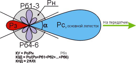
- Ku is the ratio of the adopted antenna on the main (main) petal of its DN signal power, to its own power adopted in the same place and at the same frequency of non-directional, with circular, day, antenna.
- KND - the ratio of the body angle of the entire sphere to the corporal corner of the opening of the main petal of the DN, as an assumption that its cross section is a circle. If the main petal has different sizes in different planes, it is necessary to compare the area of \u200b\u200bthe sphere and the cross section of the main petal.
- KDZD - the ratio of the signal received to the main petal of the signal power to the amount of noise power at the same frequency adopted by all side (rear and side) petals.
Notes:
- If the antenna is a range, power is considered at the frequency of the useful signal.
- Since absolutely non-directional antennas does not happen, for such a half-life linear dipole, oriented towards the electrical field of the field (by its polarization). It is considered to be equal to 1. TV programs are transmitted with horizontal polarization.
It should be remembered that ku and the CBD are not necessarily interrelated. There are antennas (for example. "Spyware" is a single-conducting antenna of a running wave, an ABB) with a high orientation, but a single or less amplification. These are looking away in the distance through a dioptric sight. On the other hand, there are antennas, for example. Z-antenna, in which a low orientation is combined with significant amplification.
About impropers of manufacture
All elements of the antennas for which the currents of the beneficial signal occur (specifically in the descriptions of individual antennas), should be connected with soldering or welding. In any precast node in the open air, the electric contact will soon break, and the antenna parameters deteriorate sharply, up to its complete disrepair.
This is especially true of zero potential points. In them, as experts say, there is a voltage assembly and duck, i.e. Its greatest value. Current at zero voltage? Nothing amazing. Electrodynamics left Ohm's law on constant current as far as the T-50 from the air serpent.
Places with dots of zero potential for digital antennas are best done bent made of solid metal. A small "creeping" current on welding when taking an analogue in the picture, most likely will not affect. But, if a digit is taken on the border of noise, then the tuner due to the "Crack" may not see the signal. Which, with a clean current in the beacon, would give a stable reception.
About soldering cable
Braid (and the central lived often) modern coaxial cables are made not from copper, but from stubborn to corrosion and inexpensive alloys. They roll badly and, if you warmly warm, you can overheet the cable. Therefore, it is necessary to solder cables with a 40-W soldering iron, a low-melting point and with flux pasta instead of rosin or alcoholifoli. Pastes do not need to regret, the solder immediately spreads through the braid veins only under the boiling flux layer.
Views of antennas
Vsevolovaya
Vesvolovaya (more precisely, frequently dependent, cn) antenna is shown in Fig. It is two triangular metal plates, two wooden slats, and many copper enameled wires. The diameter of the wire value does not have, and the distance between the seams of the wire on the rails is 20-30 mm. The gap between the plates to which other ends of the wire are soldered - 10 mm.
Note: Instead of two metal plates, it is better to take a square from one-sided foil fiberglass in the cut-cut triangles.
The width of the antenna is equal to its height, the opening angle of the canvas is 90 degrees. The cable laying circuit is shown there in Fig. The point marked with yellow is the point of quasi-zero potential. The cable braid in it is not necessary in it, it is not necessary to tight enough to tight, there will be enough containers between the braid and the web.
CNA, stretched in a window with a width of 1.5 m, takes all meter and DCM channels with almost all directions, except for the failure of about 15 degrees in the plane of the canvas. In this, its advantage in places where signals from different television steps are possible, no need to rotate. Disadvantages - single ku and zero KZD, therefore, in the zone of the interference and outside the zone of confident reception, the CNA is not suitable.
Note : There are other types of CNA, for example. in the form of a double logarphymic spiral. It is compacting the CNA of triangular cloths in the same frequency range, so it is sometimes used in the technique. But in everyday life, this advantage does not give, make a spiral chanage more difficult, with coaxial cable, harder, so we do not consider.
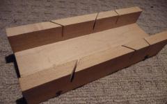
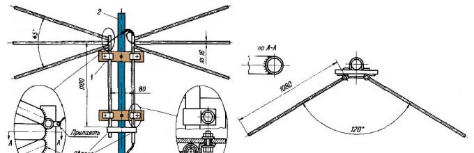
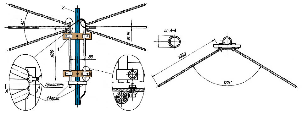
Based on the CNA, a very popular once wanted vibrator (horns, flyer, slingshot) was created, see fig. His knd and KDD is about 1.4 with a rather smooth response and linear FFH, so for the figure it would come now. But it works only on MV (1-12 channels), and digital broadcasting goes to DMV. However, on the village, with a lift of 10-12 m, it can be consolidated to receive analogue. Mast 2 can be from any material, but fastening strips 1 - from a good non-filling dielectric: fiberglass or fluoroplast with a thickness of at least 10 mm.
Beer Nobolovka
Vsevolovaya Antenna from beer cans is clearly not the fruit of wary hallucinations of a well-spawn radio amateur. It is really a very good antenna for all cases of reception, you just need to make it right. And extremely simple.
At the heart of its design, the following phenomenon: If you increase the diameter of the shoulder of the ordinary linear vibrator, then the operating bar of its frequencies is expanding, and other parameters remain unchanged. In the long-term radio communications from the 20s, the so-called is used. Dipole Napenenko, based on this principle. And the beer banks are just suitable as the shoulders of the vibrator on the DMW. In essence, CNA and there is a dipole whose shoulders are unlimited expanding to infinity.
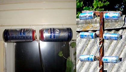
The simplest beer vibrator of two cans is suitable for room reception of analogue in the city, even without coordination with the cable, if its length is not more than 2 m, on the left in Fig. And if you collect a vertical syphanit grille from beer dipoles with a pitch to the half-wave (right in Fig.), Coordinate it and check with the help of an amplifier from the Polish antenna (it will be more about it), then thanks to the compression of the main petal of the Vertical Vertical, such an antenna will give and Good ku.
Strengthening "Pivnuhi" can still be increased by adding the KDD at the same time if the screen is made from the grid at a distance equal to half the grid steps. Mounted beer grille on a dielectric mast; Mechanical connections of the screen with mast - also dielectric. The rest is clear from the trail. Fig.
Note: the optimal number of lattice floors is 3-4. With 2 gains in strengthening it will be small, and more difficult to agree with the cable.
Video: Production of the simplest antenna from beer cans
"Setaging"
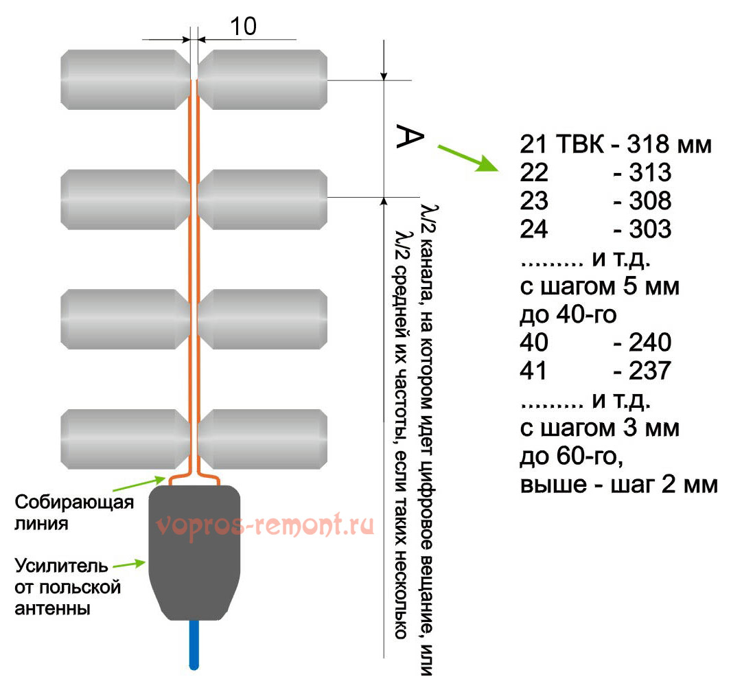
The logoeriodic antenna (LPA) is a collecting line, to which half of linear dipoles are alternately connected (i.e., pieces of conductor in a quarter of a working wave), the length and the distance between which are changed in geometric progression with the indicator less than 1, in the center in Fig. The line can be both configured (from the CZ on the opposite of the connection of the cable end) and free. LPA on a free (unconfigured) line for receiving the numbers is preferable: it comes out longer, but its frequency response and FCH are smooth, and the coordination with the cable does not depend on the frequency, so we will stop on it.
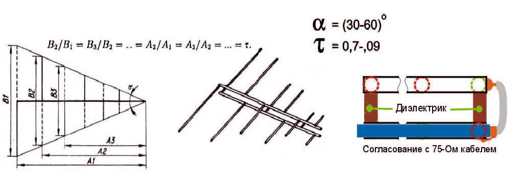
LPA may be made on any, up to 1-2 GHz, the specified frequency range. When the operating frequency changes, its active region of 1-5 dipole is shifted back and forth to the canvas. Therefore, the closer the progression rate to 1, and, accordingly, less an antenna opening an antenna, the greater the strengthening it will give, but at the same time its length increases. On dmv from the outer LPa, 26 dB can be achieved, and from room - 12 dB.
LPA, can be said, on the totality of the qualities The perfect digital antennaTherefore, we will stop on its calculation several more. The main thing is that it is necessary to know that an increase in the progression rate (Tau in Fig.) Gives an increase in amplification, and the decrease in the angle of disclosing LPA (ALPHA) increases the direction. The screen for LP is not needed, it almost does not affect its parameters.
The calculation of digital LPA has features:
- Start it, for the sake of stock in frequency, from the second length of the vibrator.
- Then, taking the reverse magnitude of the progression indicator, the longest dipole is calculated.
- After the shortest, based on the specified frequency range, dipole, add another one.
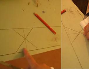
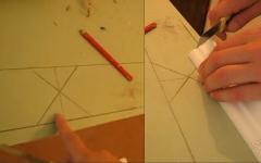
Let us explain on the example. Suppose our digital programs are in the range of 21-31 TVK, i.e. in 470-558 MHz in frequency; The wavelengths respectively - 638-537 mm. We also assume that we need to take a weak roaring signal away from the station, so we take the maximum (0.9) progression indicator and the minimum (30 degrees) angle of disclosure. To calculate, it will take half the angle of opening, i.e. 15 degrees in our case. The discontinuity can be further reduced, but the antenna length is prohibitive, according to Kotangent, will increase.
We consider B2 in fig: 638/2 \u003d 319 mm, and the shoulders of the dipole will be 160 mm, you can round up to 1 mm. The calculation will need to lead until it turns out Bn \u003d 537/2 \u003d 269 mm, and then calculate another dipole.
Now we consider A2 as B2 / TG15 \u003d 319 / 0.26795 \u003d 1190 mm. Then, through the progression indicator, A1 and B1: A1 \u003d A2 / 0.9 \u003d 1322 mm; B1 \u003d 319 / 0.9 \u003d 354.5 \u003d 355 mm. Next, in series, starting with B2 and A2, we multiply on the indicator until we do up to 269 mm:
- B3 \u003d B2 * 0.9 \u003d 287 mm; A3 \u003d A2 * 0.9 \u003d 1071 mm.
- B4 \u003d 258 mm; A4 \u003d 964 mm.
Stop, we have less than 269 mm. We check whether it will be put on strengthening, although it is so clear that there is no: to get 12 dB and more, the distance between dipoles should not exceed 0.1-0.12 wavelengths. In this case, we have for B1 A1-A2 \u003d 1322 - 1190 \u003d 132 mm, and this is 132/638 \u003d 0.21 wavelengths B1. You need to "tighten" the indicator to 1, to 0.93-0.97, so we try different while the first difference A1-A2 is not shrinking twice and more. For a maximum of 26 dB, the distance between dipoles is 0.03-0.05 wavelengths, but at least 2 diameters of the dipole, 3-10 mm per DMV.
Note: the remainder of the line for the shortest dipole, cut, it is only needed for the calculation. Therefore, the real length of the finished antenna will be only about 400 mm. If our LAP is outdoor, it is very good: you can reduce the discontinuity, having gained great direction and protection against interference.
Video: Antenna for digital TV DVB T2
About line and mast
The diameter of the LAP line tubes on the DMW is 8-15 mm; The distance between their axes is 3-4 diameters. We take into account yet that thin cables are "shoelaces" give such attenuation on the meter that all the antenna-amplifying tricks will come to no. Coaxial for the outer antenna must be taken a good, with a diameter of the shell from 6-8 mm. Those., Tubes for the line must be thin-walled solrencies. Touch the cable to line outside it is impossible, the quality of LPA will fall sharply.
It is necessary to mount the outdoor LPA to the mast, of course, for the center of gravity, otherwise the small sailboat of the LPA will turn into a huge and shaking. But it is impossible to connect a metal mast directly with the line too: it is necessary to provide a dielectric insert at least 1.5 m long. The quality of a large role dielectric is not playing here, a poles and painted tree will go.
On the Antenna "Delta"
If DMV LPA is consistent with the cable amplifier (see further, about Polish antennas), then the shoulders of a meter dipole, linear or fan, like "slingshot" can be attached to the line. Then we get a universal MV-DMV antenna of excellent quality. This solution is used in the popular "Delta" antenna, see Fig.
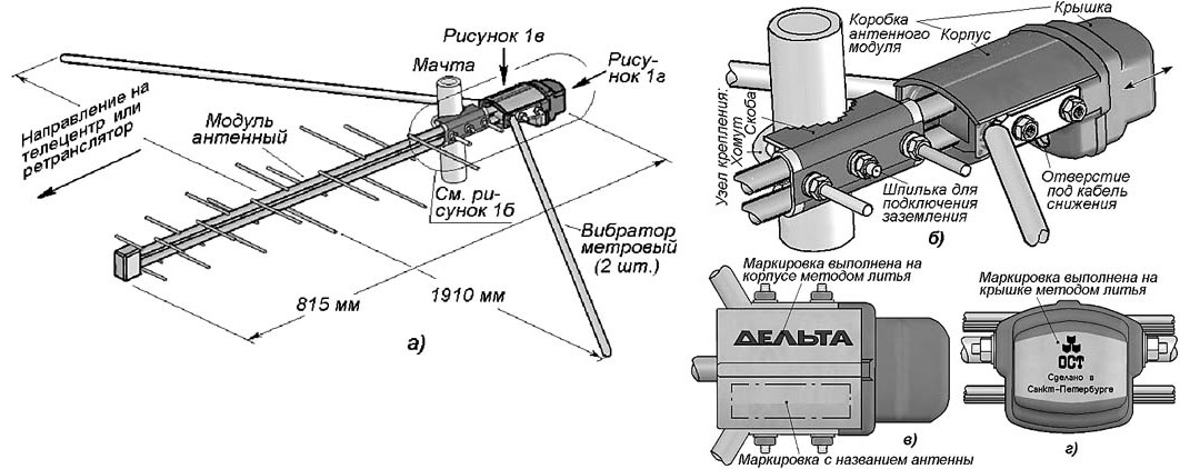
Delta Antenna
Zigzag on the air
The z-antenna with the reflector gives strengthening and the CDDs are the same as LPA, but the main petal of its bottoms is more than twice as wide horizontally. It may be important to the village when there is a TV reception from different directions. And the decimeter z-antenna has small in terms of size, which is essential for room reception. But its working range is theoretically not impaired, overlapping frequency while saving acceptable parameters for numbers - up to 2.7.
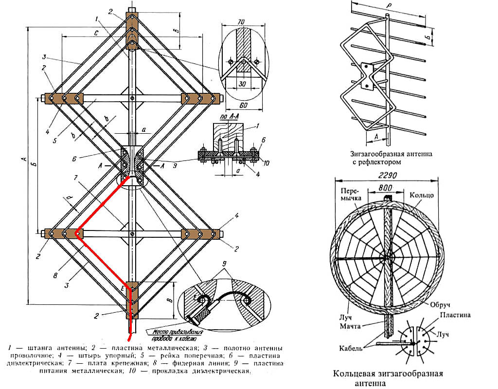
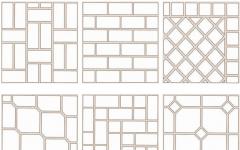
The design of the Z-antenna MV is shown in Fig; Red highlighted the path of cable laying. In the same place below - a more compact ring version, in the spaciousness - "Spider". It is clearly clear that the z-antenna was born as a combination of CNA with a range of vibrator; There is something in it from the rhombic antenna, which does not fit into the topic. Yes, the "Spider" ring does not have to be wooden, it may be a metal hoop. "Spider" takes 1-12 mV channels; DN without a reflector - almost circular.
The classic zigzag works or 1-5, or 6-12 channels, but for its manufacture, only wooden rails are needed, the copper enameled wire Cd \u003d 0.6-1.2 mm and a few trimming of foil fiberglass, so we give dimensions through Fraction for 1-5 / 6-12 channels: a \u003d 3400/950 mm, b, C \u003d 1700/450 mm, B \u003d 100/28 mm, B \u003d 300/100 mm. At the point E - zero potential, here you need to solder a braid with a metallized support plate. The dimensions of the reflector, also 1-5 / 6-12: a \u003d 620/175 mm, b \u003d 300/130 mm, r \u003d 3200/900 mm.
Range z-antenna with a reflector gives a 12 dB gain, configured to one channel - 26 dB. To build a single-channel based on the band zigzag, you need to take the side of the square of the canvas in the middle of its width in a quarter of the wavelength and recalculate in proportion to all other dimensions.
People's Zigzag
As you can see, the Z-Antenna MV is a rather complex structure. But her principle shows itself in all shine on the DMW. The Z-Antenna of the DMW with capacitive inserts, combining the dignity of the "classics" and "spider", is so simple that she still has deserved the title of folk, see fig.
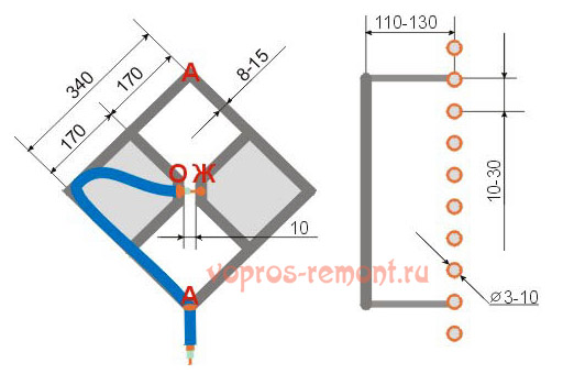
Material - copper tube or aluminum leaf thick from 6 mm. Side squares are solid metal or tightened by a grid, or closed with tin. In the last two cases, they need to be sued along the contour. Coaxial can not be changed sharply, so we lead it so that it reaches the side angle, and then did not go beyond the capacitive insert (side square). In t. A (zero potential), the cable braid is electrically connected with the web.
Note: aluminum is not soldered by ordinary solders and fluxes, so aluminum "folk" is suitable for an outdoor installation only after sealing electrical connections with silicone, it is all on the screws.
Video: Example of a double triangular antenna
Wave canal
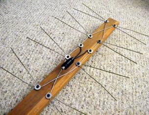
Antenna Wave Channel (AVC), or antenna Udo-Yagi from available to independent manufacture is able to give the largest ku, CBD and KDD. But it can only take the digit on the DMW only on 1 or 2-3 adjacent channels, because Refers to the class of acutely configured antennas. Its parameters outside the setting frequency deteriorate sharply. AVC is recommended to apply with very bad conditions of reception, and for each TCE to do separate. Fortunately, this is not very difficult - AVK is simple and cheap.
At the heart of WCC - "Sgsh" the electromagnetic field (EMF) signal to the active vibrator. Externally, small, light, with minimal sailboat, AVC may have an effective aperture in tens of operating frequency waves. Cropped and therefore having an capacitive impedance (full resistance) directors (director) direct EMF to an active vibrator, and the reflector (reflector), elongated, with inductive impedance, discarded something that slipped past. The reflector in AVC is needed only 1, but directors can be from 1 to 20 or more. What they are more, the higher the strengthening of AVK, but already the band of its frequencies.
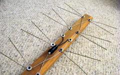
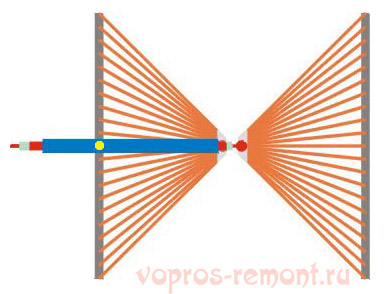
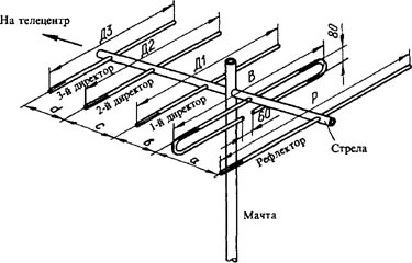
From interaction with the reflector and directors, the wave resistance of the active (from which the signal is removed) the vibrator falls the more, the closer to the maximum gain the antenna is configured, and the coordination with the cable is lost. Therefore, the active dipole AVC is made by loop, its initial wave resistance is not 73 ohms, like a linear, and 300 ohms. At the cost of its decline to 75 ohms AVK with three directors (five-element, see fig. Right) It is possible to configure almost the maximum gain of 26 dB. Characteristic for AVC DN in the horizontal plane is shown in Fig. At the beginning of the article.
The elements of AVC are connected to the arrow at the points of zero potential, so the mast and boom can be any. Propylene pipes are very well suited.
The calculation and setting of AVK under analogue and the figure are somewhat different. Under the analogue of the wave channel, it is necessary to count on the carrier frequency of the image FD, and under the figure - on the middle of the TWEC FC spectrum. Why so - here to explain, unfortunately, there is no place. For the 21st TVK FD \u003d 471.25 MHz; FC \u003d 474 MHz. The DMW TDC is located close to each other after 8 MHz, so their configuration frequencies for AVC are calculated simply: fn \u003d fd / fc (21 TVK) + 8 (N - 21), where N is the number of the desired channel. Eg For 39 TVK FD \u003d 615.25 MHz, and fc \u003d 610 MHz.
In order not to record the set of numbers, it is convenient to express the size of AVC in the fractions of the working wave length (it is considered as l \u003d 300 / f, MHz). The wavelength is made to designate a small Greek letter of the lambda, but because there is no default in the Internet of the Greek alphabet, we conventionally denote by her big Russian L.
Sizes optimized under the figure of AVC, in fig. Such:
- P \u003d 0.52l.
- B \u003d 0.49l.
- D1 \u003d 0.46l.
- D2 \u003d 0.44l.
- D3 \u003d 0.43l.
- a \u003d 0.18l.
- b \u003d 0.12l.
- c \u003d d \u003d 0.1l.
If you do not need a big gain, but it is more important to reduce the dimensions of AVK, then D2 and D3 can be removed. All vibrators are performed from a tube or a rod with a diameter of 30-40 mm for 1-5 TVK, 16-20 mm for 6-12 TVs and 10-12 mm per DMV.
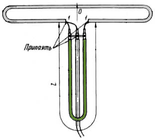
AVC requires accurate agreement with the cable. It is the negligent fulfillment of the device for coordination and symmetrization (ICS), most of the failures of lovers are explained. The simplest UCU for AVK - U-loop from the same coaxial cable. Its design is clear from fig. on right. The distance between the signal terminals 1-1 140 mm for 1-5 TVK, 90 mm for 6-12 TVs and 60 mm per DMV.
Theoretically, the length of the knee L should be half the length of the working wave, and this is central to most publications on the Internet. But the EMF in the U-loop is concentrated inside the insulation of the cable, so it is necessary (for the figure it is especially necessary) to take into account its shortening coefficient. For 75-ohm coaxials, it fluctuates in the range of 1.41-1.51, i.e. l You need to take from 0.355 to 0.330 wavelengths, and take sure that AVK was AVK, and not a set of glands. The exact value of the shortening coefficient is always in the Cable certificate.
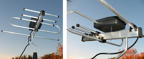
Recently, the domestic industry began to produce redirected AVC for numbers, see fig. Idea, I must say, excellent: Moving elements on arrows, you can accurately configure an antenna for local reception conditions. Better, of course, to make this specialist - the elemental setting of AVC is interdependent, and the amateur is certainly confused.
About "Poles" and amplifiers
Many users have Polish antennas, previously adopted analogue, the digit to take refuse - rushes, or even disappears. The reason, I apologize, a sick-commercial approach to electrodynamics. Sometimes sometimes it happens for colleagues that slept such a "miracle": the response and FFH are similar to the hedgehog-psoriaznik, or a horsepior comb with broken teeth.
The only thing that is good in the "Poles" is their antenna amplifiers. Actually, they do not give SIM products to sneak. Amplifiers "Schek", firstly, broadband low-noise. And, more importantly - with high-resistance. This allows for the same tension of the EMF signal on the air to submit to the input of the tuner several times more of its power, which allows the electronics to "pull out" the figure from very ugly noise. In addition, due to the large input resistance, the Polish amplifier is the perfect UCU for any antennas: that neither cling to the entrance, at the exit - exactly 75 ohms without reflects and spinning.
However, with a very bad signal, outside the zone of confident reception, the Polish amplifier no longer pulls. It is supplied to it on the cable, and the diet is taking a 2-3 dB signal-to-noise relationship, which can not be enough for the figure to go to the outback itself. Here you need a good TV signal amplifier with separate meals. It will most likely be located, near the tuner, and the UCU for antenna, if required, will have to do separately.
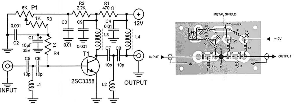
The scheme of such an amplifier, which showed almost 100% repeatability even when performing novice radio amateurs, is shown in Fig. Adjusting gain - P1 potentiometer. Throtes of junction L3 and L4 - standard purchased. Coils L1 and L2 are performed in size on the mounting scheme on the right. They are part of the bandwidth filters of the signal, so small deviations of their inductance are not critical.
However, the mounting (configuration) of the installation must be observed for sure! And the metal screen (Metal Shield), separating the output chains from other schemes, is also required.
Where to begin?
We hope that experienced wizards will find a certain amount of information useful information in this article. And beginners, not yet feeling the air, it is best to start with the beer antenna. The author of the article, by no means an amateur in this field, at one time was quite surprised: the simplest "beer" with ferrite agreement, as it turned out, and MV takes no worse than the "slingshot". And what should be done and the other - see text.