The era of digital signals has arrived. All broadcasting TV companies began to work in a new format. Analog TVs are living out their days. They are still in working order and are available in almost every family.
In order for the old models to successfully finalize their resource, and people can use them when watching digital broadcasting, it is enough to connect the DVB-T set-top box to the TV receiver and catch the TV wave signals with a special antenna.
Any home craftsman is able not to buy an antenna in a store, but to make it with his own hands from available tools for watching digital TV programs at home or in the country. The two most affordable constructs are described in this article.
A bit of theory
Principle of operation of an antenna for digital packet television
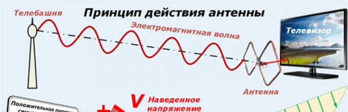
Any television signal propagates in space from the emitters of the transmitting television tower to the television antenna by a sinusoidal electromagnetic wave with a high frequency measured in megahertz.
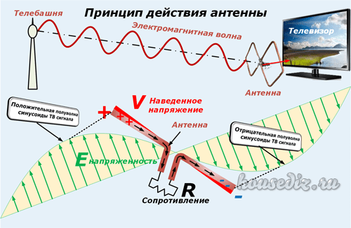
When an electromagnetic wave passes through the surface of the receiving antenna beams, a voltage V is induced in it. Each half-wave of a sinusoid forms a potential difference with its own sign.
Under the influence of the induced voltage applied to the closed receiving circuit of the input signal with resistance R, an electric current flows in the latter. It is amplified and processed by the digital TV circuitry and output to the screen and speakers as picture and sound.

In this way, the transmitters direct the emitting signals.
And users just need to rotate the receiving antenna in the desired plane to maximize the removal of the power potential.
Digital Packet TV Antenna Requirements
TV transmitters spread their signal-waves over short distances, limited by the line-of-sight from the top point of the TV tower emitter. Their range rarely exceeds 60 km.
For such distances, it is sufficient to provide a small power of the emitted TV signal. But, the intensity of the electromagnetic wave at the end of the coverage area should form a normal voltage level at the receiving end.
A small potential difference is induced at the antenna, measured in fractions of a volt. It creates currents with small amplitudes. This imposes high technical requirements on the assembly and workmanship of all parts of digital reception devices.
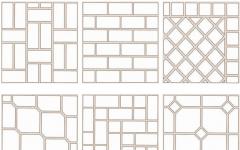
Antenna design should be:
- made accurately, with a good degree of accuracy, excluding the loss of electrical power of the signal;
- directed strictly along the axis of the electromagnetic wave coming from the transmitting center;
- oriented by the type of polarization;
- protected from extraneous interference signals of the same frequency coming from any sources: generators, radio transmitters, electric motors and other similar devices.
How to find out the initial data for calculating the antenna
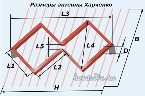
The main parameter influencing the quality of the received digital signal, as can be seen from the explanatory first figure, is the length of the electromagnetic radiation wave. Symmetrical arms of vibrators of various shapes are created under it, the overall dimensions of the antenna are determined.
The wavelength λ in centimeters can be easily calculated using a simplified formula: λ = 300 / F. It is enough just to find the frequency of the received signal F in megahertz.
We will use the search for GUGL for this and ask him for a list of regional TV communication points for our area.
As an example, a fragment of the data table for the Vitebsk region is shown with a red rectangle highlighting the transmitting center in Ushachi.
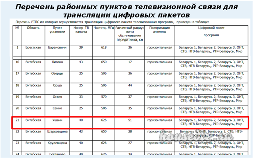
Its wave frequency is 626 megahertz, and the type of polarization is horizontal. This data is quite enough.
We carry out the calculation: 300/626 = 0.48 m. This is the length of the electromagnetic wave for the antenna being created.
We divide it in half and we get 24 cm - the required half-wave length.
The simplest TV antenna for digital television
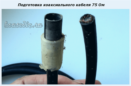
It requires a piece of coaxial cable with a characteristic impedance of 75 ohms and an antenna plug. I managed to find a ready-made two-meter piece in the old stock.
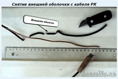
From the free end, I cut off the outer shell with an ordinary knife. I take the length with a small margin: when setting up it is always easier to bite off a small piece.
Then I remove the shielding layer from this section of the cable.
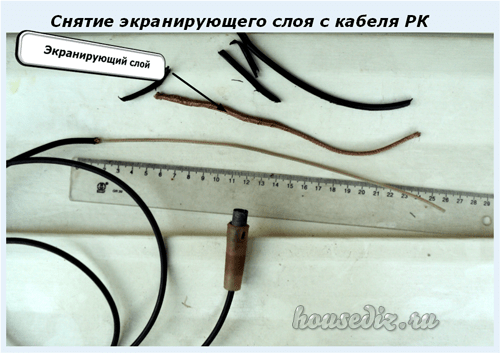
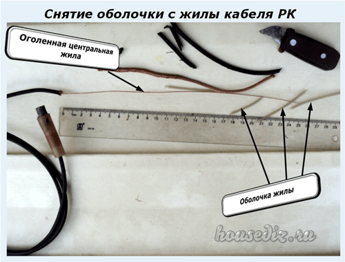
The work is done. It remains to insert the plug into the connector on the TV signal set-top box and direct the bare wire of the inner core across the incoming electromagnetic wave, taking into account the horizontal polarization.
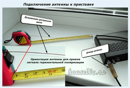
The antenna should be placed directly on the windowsill or fixed to the glass, for example, with a piece of tape or tied to the blinds mount. Reflected signals and interference can be shielded with a strip of foil located at a short distance from the central core.
Such a design is done literally in a dozen minutes and does not require special material costs. It's worth trying it. But, it is capable of working in the area of reliable signal reception. My building is shielded by a mountain and a multi-storey building. The transmitting TV tower is located at a distance of 25 km. Under these conditions, the digital electromagnetic wave is reflected many times and poorly received. I had to look for another technical solution.
And for you on the topic of this design, I propose to watch the video of the owner Edokoff "How to make an antenna for digital TV"
Antenna Kharchenko at 626 MHz
To receive analogue TV broadcasting signals of various wave frequency ranges, the design of a zigzag broadband antenna used to work well for me, which does not require complex manufacturing.
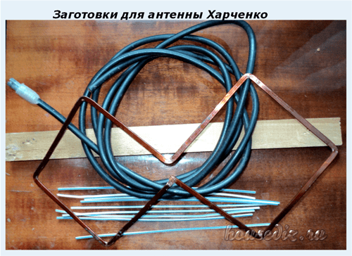
I immediately remembered one of their effective varieties - the Kharchenko antenna. I decided to use its design for digital reception. I made the vibrators from a flat copper bus, but it is quite possible to get by with a round wire. This will make it easier to bend and align the ends.

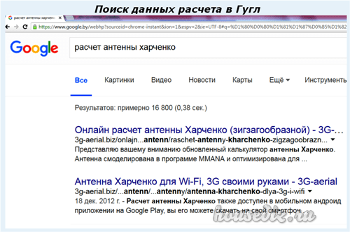
We choose any site you like and perform an online calculation. I went to the first one that opened. Here's what he calculated for me.
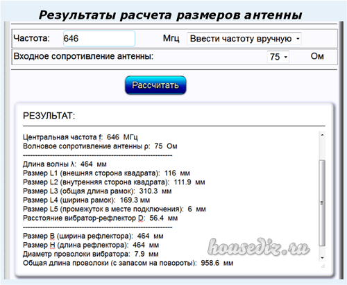
I presented all his data with a picture with the designation of the name of the dimensions of the Kharchenko antenna.
Manufacturing of antenna structure parts
I took the information provided as a basis, but did not exactly maintain all the dimensions. I know from previous practice that the antenna works well in the broadband wavelength range. Therefore, the dimensions of the parts were just slightly overestimated. The half-wave of each harmonic of the sinusoid of the electromagnetic TV signal will fit into the shoulder of each vibrator and will be received by it.
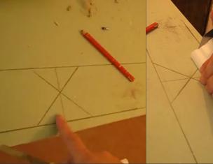
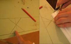
Based on the selected data, I made blanks for the antenna.
Vibrator design features
The connection of the ends of the shank for the figure-eight is created in the center during the bending stage. I soldered them with a soldering iron.
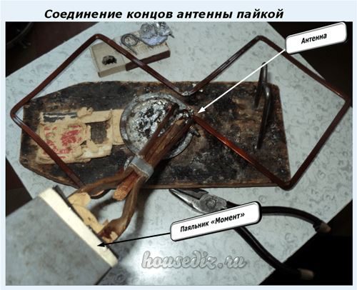
I have it created according to the "Moment" principle, made by hand from old transformers, it has been working for two decades. They even soldered a copper wire 2.5 squares in a thirty-degree frost. Works with transistors and microcircuits without burning them out.
I plan to describe its design in a separate article on the site in the near future for those who also wish to make it with their own hands. Follow the publications, subscribe to notifications.
Connecting the antenna cable to the vibrator
The copper core and braid were simply soldered to the metal of the figure eight from different sides along its center.
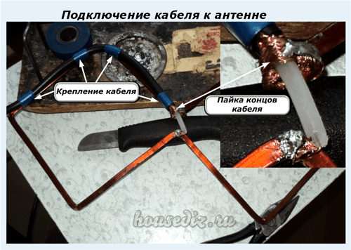
The cable was tied to a copper bus, bending it in a loop in the shape of a semi-square vibrator. In this way, the cable and antenna impedances are matched.
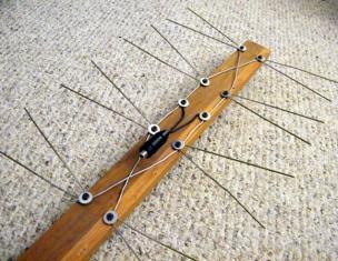
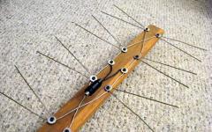
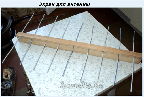
Shielding grid design
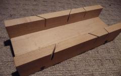
In fact, Kharchenko's antenna often works fine without shielding the signals, but I decided to show its manufacture. I took a wooden block for the base. I did not paint and saturate with varnish: the structure will be used indoors.
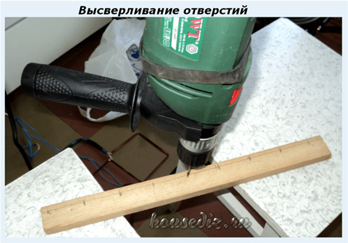
In the back of the block I drilled holes for attaching the screen wires and inserted them, and then jammed them.
The result is a screen for Kharchenko's antenna. In principle, it can be made of a different design: cut out of a piece of frontal armor of a tank or cut out of food foil - it will work in about the same way.
On the reverse side of the bar, I fixed the structure of the vibrator with a cable.
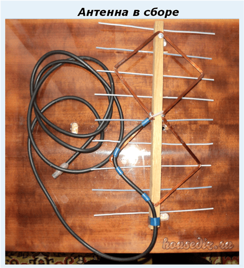
The antenna is ready. It remains to install it on the window for operation in horizontal polarization.

In both cases, the amplifier will do its part and raise the power. Moreover, the TV will clearly perceive and display the weakened signal, and with the reinforced "karyabola" there will be playback problems.
To eliminate such interference waves are designed:
- h / h filters;
- screens.
They need to be measured with an oscilloscope, and the ways of using different designs should be analyzed on a case-by-case basis. The antenna is not to blame here.