When the pressure in the hydroaccumulator is greatly reduced, the relay activates the pump, respectively, and it turns off the equipment when it reaches the critical pressure mark. As a result, even a small failure in the work of the parts will affect the functionality of the whole system of water supply to the house. Fortunately, this is not critical, and any failure can be corrected by yourself using the adjustment. Therefore, it is necessary to thoroughly understand the features of the adjustment process, connection and standard relay settings.
Design
In most cases, the pressure switch consists of a metal base, to which a membrane cover is attached below (which, in turn, hides the diaphragm and the piston). There is also a quick-release nut on the lid for connecting to an adapter for pumping equipment, and in the upper part of the relay there is a contact group and a terminal block (for connecting the pump station, grounding, etc.), as well as a pair of spring regulators. All these working parts are covered on top with a plastic cover, it is attached to the screw of a large regulator. If necessary, you can remove the cover yourself; you only need a screwdriver or a wrench.

Different models of the pressure switch may differ in the form, arrangement of parts, sizes, but almost all of them have the above design. True, some manufacturers equip their products with additional details, such as the lever of protection against the "dry run", etc.

Operating principle
In the pumping station there is a hydroaccumulator (pressurized tank for liquids), a unit (pump of vibrating or centrifugal type), as well as a pressure switch that regulates the operation of these parts.
Interestingly, the principle of the relay is determined by the operation of the station itself, which consists of several stages: turning on the pumping equipment - filling the tank - turning off. But when it is necessary to start and stop the pump determines the pressure switch.

In this case, the procedure for deciding whether to start or stop the pump is done on the basis of monitoring such data: the minimum and maximum pressure in the system. Also, the effect of the relay is influenced by such values as the difference between the lowest and the highest pressure, as well as the maximum possible pressure in the storage tank.
The minimum pressure in most cases is 1.5 atmospheres. This means that if the indicator drops below the stated 1.5 atmospheres, then the relay will close the pump by closing the contacts and start pumping the liquid.
As for the maximum pressure, this indicator is rarely above 4 atmospheres. This means that when this level is reached, the contacts open in the relay and the pump stops working actively.

Of these two quantities, we can get the third — the difference between the lowest and the highest pressure, which is 2.5 atmospheres. In the process of adjustment, it is necessary to focus on this indicator, adjusting the desired difference from the minimum pressure.
The maximum indicator of pressure in the storage tank will be 5 atmospheres. This means that if the pressure reaches this indicator, the pumping equipment will shut off independently, regardless of the pressure difference.
Check of pressure in the hydroaccumulator
The very first adjustment of the element occurs at the enterprise where pumping stations are produced. Therefore, all standard settings of 1.5 atmospheres of minimum pressure and 2.5 atmospheres of difference are also called “factory”. The actual connection of the pressure switch to the pumping equipment occurs at the last stage of the system assembly. In the meantime, the unit will buy, and it will be installed in the house, it will take a long time, so the factory settings may be lost.
After purchasing the pump system, you need to check the pressure indicator, which is created in the tank by the manufacturer. In most cases, this characteristic is at the level of 1.5 atmospheres, but it must be borne in mind that during storage in the warehouse and during transportation, some of the air could escape from the storage tank.
Experts to verify this characteristic are advised to use a car manometer with a detailed graduated scale to get an accurate result. In a set to the pump equipment, the manufacturer can give a plastic pressure gauge, but such a device is unlikely to be able to accurately determine the pressure characteristic in the hydraulic tank. There is another type of device - electronic pressure gauges, but their work often depends on the charge level and air temperature. Considering also the fact that the electronic version will cost a lot and will soon break, it is better to take an ordinary automobile gauge in a steel case.

Experts advise the use of mechanical devices because they are more reliable and durable, compared to expensive and not quite accurate electronic models, or plastic counterparts from the Middle Kingdom, which will quickly break.

To check the pressure in the tank, first you need to remove the special cap under which the nipple is located, then connect a pressure gauge to it and measure the characteristic. The lower the pressure, the more liquid in the tank can be equipped. For normal water pressure, it is advised to keep the pressure within 1.5 atmospheres. Some experts argue that even with 1 atmosphere it is easy to provide all household water needs.
If the pressure in the system is high, then the pump will work more often and, accordingly, will wear out faster, but this will create a head of approximately the same capacity as in the urban water supply system. This is very useful and will allow you to install a shower with a hydromassage function or even a whirlpool. If the pressure is too low, the water procedures will be limited only to a bath, and you will have to wait a long time to fill the bowl with water.

It should be borne in mind that professionals do not advise to pump the accumulator too much or reduce the pressure to an indicator below 1 atmosphere. This is fraught with the fact that there is not enough liquid in the tank, or the rubber pear may even be damaged.
Pressure switch setting
Before you make the adjustment, you must dismantle the cover, under it will be visible two springs with nuts: large and small. If you turn the large nut, the lower pressure in the system (P) will be adjusted. When turning the small nut, you can control the pressure difference (ΔP). The reference figure will be the location of the dimensional spring, thanks to it you can adjust the limit of the minimum pressure characteristic.

When the pressure inside the tank has reached the required level, the tank must be connected to the system and put into operation. It is necessary to observe the indicators of the water gauge. It is worth noting that the instructions and other documents for pumping equipment spell out the characteristics of the working and maximum pressure characteristics, as well as the allowable flow rate. These recommendations should not be exceeded even during adjustment of the device. If during the execution of these actions, the mechanism reaches the operating pressure of the accumulator or the limiting value of the pump, then the unit must be turned off manually. The fact that the maximum pressure level has been reached is indicated by the stop of pressure increase.

In fact, models of units for domestic purposes do not have such a high capacity to maximally pump capacity. In most cases, the difference between the set starting and stopping pressure characteristics is only 1-2 atmospheres, which creates safe and normal conditions for the use of pump systems.
When the lower pressure reaches the set value, the pump should be turned off immediately. Further, the pressure accumulator pressure switch setting occurs in several stages:
- Carefully turn the small nut (pressure difference control) until the system turns on.
- In the next step, you need to open the water so that the mechanism is completely free from liquid.
- When the lower pressure switch starts to work, it means that the lower pressure indicator has been reached. It should be borne in mind that the pressure of switching on pumping equipment should be 0.1 - 0.3 atmospheres greater than the indicator in an empty accumulator. This will prevent damage to the rubber "pear".
- Next, you need to unscrew the large nut (lower pressure control).
- At this stage, the pumping equipment is turned on again, it should work until the pressure rises to the required value.
- In the end, you need to once again adjust the small nut, and the procedure for setting up the accumulator is completed.

In addition to making the primary adjustment when connecting the relay to the pumping equipment, experts advise, from time to time to check the operation of the mechanism and adjust it. At least once every three months you will need to completely drain the fluid from the accumulator, and check the pressure indicator. Adjustment is carried out by pumping (to increase) or by bleeding (to reduce).
If you decide to customize the operation of the pump system relay, then you need to consider some features of the mechanism:
- Experts do not advise to adjust the upper pressure indicator, which will be more than 80% of the maximum allowable pressure for a specific model of the relay. In order to avoid mistakes, it is necessary to familiarize yourself with the technical documentation of the device, this indicator can also be indicated on the packaging, it is usually 5 - 5.5 atmospheres. If your home needs higher pressure, then you need to pick up the appropriate relay.

- Before adjusting the highest pressure indicator when turning on the pumping equipment, it is necessary to study its characteristics and find out whether the unit can develop such an indicator. When the pumping system can not cope with this task, it will act without interruption, because it will not be able to provide the necessary pressure. The pressure of the equipment is noted in meters of water column and approximately one unit according to this indicator is equal to 0.1 atmosphere. It is also worth considering the possible hydraulic losses in the mechanism.
- When adjusting the pressure in the mechanism, it is not necessary to tighten the nuts completely, in which case the relay will simply stop working.
Indicator of air pressure in the hydroaccumulator
This indicator has a strong influence on the operation of pumping equipment, but does not control the adjustment of the relay. It will, in any situation, begin operation at a configured lower and upper pressure indicator, and this does not depend on the characteristics of the air in the tank.
If there is no air inside the tank, it will pull the filling with it. Considering the fact that the water is almost not compressed, the pressure in the mechanism will reach the “upper” indicator immediately, and the pump will immediately turn off when the valve is closed. Also, each activation of the water intake point will instantly turn on the pump, because the pressure drops to the minimum value. This means that the system will work as well as it would have done without hydro. Too low air pressure will pull the membrane over itself, and under reduced pressure the tank will not be filled with liquid enough, it will completely replace the air.

In order for the pumping system to work in optimal mode and the diaphragm is not damaged, it is recommended to set the air pressure to 1/10 less than the minimum lower pressure. In such a situation, the capacity will normally be filled with liquid, and the membrane will not suffer from the strong stretching. In this case, pumping equipment will start at intervals that are equal to the pressure difference indicator.
It should also be borne in mind that checking the air pressure in the accumulator of the pumping system is necessary in the absence of water pressure. This means that you need to open the bottom valve of the mechanism, and drain the liquid from there.
If you take into account all the advice of experts, then setting up the pressure relay will not bring any problems, and the equipment will last for a very long time without the need for repairs. If there is no confidence in their abilities, then it is better to invite the masters, they will set up the system in a matter of minutes.
Video
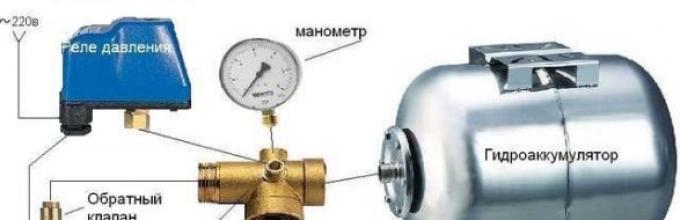
The main elements of an autonomous pumping station are a pump, a storage tank, a pressure switch for a hydraulic accumulator and a check valve. The pressure unit pumps the specified amount of water into the network. The accumulator accumulates and maintains a constant pressure to supply water to the consumer. The control unit provides a stable operation cycle of the cold water supply system equipment. Let's take a closer look at where it is applied and how to set up the hydroaccumulator and pressure switch.

Accumulator in the cold water system
Direct connection of a submersible or surface pump causes unstable water supply. The pressure unit is idling with minimal water consumption. The presence of a gravitational or pneumatic accumulator in the system does not require constant operation of the primary pressure pump. Reserve capacity maintains a constant flow of water for household and drinking needs. The supply of water reduces the dependence of individual water supply on external factors.
The gravitational design of the accumulator is an atmospheric capacitance with a float level sensor. An open tank is installed in the attic of the house, above the water points. The pressure in the system creates the weight of the liquid column. The operation of the pump is controlled by a float mechanism or level sensors.

Modern hydraulic accumulators for autonomous water supply work due to overpressure in the air chamber. The principle of operation of pneumatic batteries is based on the interaction of compressed air and water. The pump pumps water into a rubber bulb that is inside the case. The volume of the air chamber decreases, and the pressure increases. In the intervals between the inclusions of the unit, the air pushes a supply of water from the membrane into the network of the consumer.
Water does not come into contact with the inner walls of the sealed container. The air chamber separates the membrane from the metal housing. If the hydroaccumulator is used in the drinking water supply system, then the membrane material is chemically neutral rubber. When using a battery tank in a heating or hot water system, membranes with high resistance to high temperatures are used.

There are vertical and horizontal models of pneumatic accumulating tanks of various capacities. The connection of the hydroaccumulator determines the type of pump and the model of the drive. Horizontal tanks are used for remote surface units. The pressure blower is installed on the platform, in the upper part of the storage housing (i.e. the cylinder is below the self-priming pump).
Pumping stations with submersible units are completed with vertical drives. The accumulator is located above the depth pump installation level.
The volume of the hydropneumatic storage tank depends on the hourly flow of water, the power and frequency of the pump on, the height of the piping system. The greater the water consumption and the lower the pressure drop on the on / off of the pump, the greater the capacity of the hydroaccumulator.

Structural elements of the hydroaccumulator:
- sealed metal casing, designed to work under pressure (1.5? 6 atmospheres);
- elastic membrane - internal capacity for water supply;
- a flange with a valve for fixing the membrane to the body and filling it with water;
- nipple for air injection into the balloon air chamber;
- a valve to release air from the water chamber (for hydraulic accumulators whose volume exceeds 100 liters);
- bracket for mounting a small container on the wall or supporting legs, with mounting rubber gaskets for larger capacity models;
- the horizontal tank kit includes a support bracket for joint installation of a surface pump with a hydraulic accumulator and a pressure switch.

Accumulator volume calculation
The hydroaccumulator selection method is designed for individual houses that consume a large amount of water (sewage, bathroom, shower, several mixers, bidet, washing machine and dishwasher). By the number of points of water distribution determine the total coefficient of consumption and the maximum consumption of water for drinking needs. The volume of the accumulator is determined by the formula:
V is the volume of the hydroaccumulator, l;
Qmax - maximum water consumption for household and drinking needs, l / min;
a - the number of system starts per hour (the recommended value of 10 starts);
Pmin - pump start pressure, atm .;
Rmax - pressure off the pump, atm .;
Ro is the pressure of the air chamber of the hydroaccumulator, atm.

Standard installation of water supply for a small house with seasonal accommodation, as a rule, is equipped with a 24-liter hydroaccumulator. For a house with more than three paring points, choose a 50-liter drive. And in the technical passport of the equipment, the manufacturer indicates the total volume of the cylinder (the air chamber as well).
Adjustment of working pressure of the hydroaccumulator
For domestic water supply of one-story houses, the pressure in one atmosphere is considered sufficient. However, it should be borne in mind that the air pressure of the air chamber must exceed the static pressure value of the highest water takeoff point.
The maximum value of the shut-off pressure depends on the pressure characteristics of the pump. The pressure that pumps the pump, divided by 10, corresponds to the value of the upper threshold for the automatic water supply system. The correction is made on the linear hydraulic resistance, the actual voltage of the electrical network, the technical condition of the equipment and the height of the water supply system at home.

The recommended difference between the on and off pressure of the pump for autonomous water supply is 1.0? 1.5 atmospheres. Increasing the factory setting (1.5 atmospheres) will reduce the reserve volume and increase the pressure in the system. High cold water supply pressure increases consumption, leads to wasteful use of energy resources.
The formula for calculating the magnitude of the required pressure in the accumulator:
Hmax is the height in meters from the center line of the hydroaccumulator to the upper point of the water takeoff (for a two-story private house 6–7 meters).
The air pressure in the air chamber of the damper tank is checked and adjusted before installation, if the settings fail or when the water supply is broken. During the adjustment, the power supply to the pumping station is disconnected from the mains; the water from the accumulator is drained.

The pneumatic valve of the air chamber is located under the decorative cap on the tank body. Compliance or deviation of pressure from the specified operating parameters is determined using a pressure gauge connected to the spool. According to the measurement results, excess air is released or air chamber pressure is pumped up with a car pump.
If the adjustment of the operating parameters of the accumulator did not bring the desired result, then check the settings of the pressure switch.
Pressure switch device for hydroaccumulator
A pressure switch controls the operation of the pump and regulates the filling of the pneumohydraulic accumulator. The device integrates, controls and regulates the operation of the equipment of the cold water supply system.
The appearance of the pump control unit resembles a small plastic box. The device is mounted at the entrance to the storage tank. The pressure switch for the hydroaccumulator consists of a mechanical and an electrical part.

Elements of a standard pressure switch design:
- plastic case (cover with screws and base);
- metal membrane cover (with nut for connection to the pipeline);
- rubber membrane;
- brass piston;
- two threaded studs and nuts;
- large and small adjusting springs;
- base metal plate;
- articulated platform;
- electrical contact assembly with a flat spring;
- cable clamps;
- terminal block.

The spring adjustment mechanism and the connection box are protected by a plastic cover. The metal base plate at the bottom is supported by a plastic case. The base separates the working body (the membrane with a piston) from the actuator (a hinged platform, two adjusting springs on the studs and an electrical contact assembly).
The electrical part of the water pressure switch is a two-contact switching relay of electrical circuits. The legs of the electrical contact assembly are clamped between the metal base plate and the plastic case. Two couplings for clamping the cable (from the mains and the power supply line of the pump) and the relay connection to the hydraulic accumulator are located on the base of the plastic housing.
Standard inlet diameter? inches On the instrument side, the internal cross section of the attachment nut to the adapter is limited by a rubber membrane. The reciprocating movement of the elastic membrane is communicated to the brass piston, which transmits the force to a hinged metal platform.

From above, on the moving edge of the platform, a large and small spring is pressed against the force of the piston. The degree of compression of the large spring regulates the moment of switching on the pump. The range of deformation of the small spring provides off the pressure unit.
Ways of connecting the pressure switch to the hydroaccumulator
There are schemes for connecting the pressure switch to the hydroaccumulator for water and electricity.
How to connect the water pressure switch?
The connecting pipe of the connection node of the pressure accumulator of the accumulator to the pipeline is rigidly fixed. The device is assembled. Before assembly, sufficient space must be provided to allow the housing to rotate when mounting the pressure switch.
The device is screwed onto a separate thread inserted into the pipeline or mounted directly on the outlet of the accumulator through a special fitting. A five-outlet nipple allows you to install a test gauge next to the pump control device.

How to connect the pressure switch to the hydroaccumulator on the electrical part?
Direct activation of the pressure switch is produced from the mains 220V, provided that the operating current of the pump does not exceed 10 Amps.
Before connecting the cable, remove the protective plastic cover from the device. The electric cable of the power line or pump is driven into the appropriate coupling. Outside, the wire is fixed with a nut with a plastic crimp ring. The designation of contact groups is indicated on the housing. The end of the cable is divided into conductors. Phase, neutral, grounding stripped of insulating braid and connected to the terminals of the contact group.

Regulation of the pressure switch for the hydroaccumulator
The relay controls the minimum and maximum pressure in the storage tank, and maintains the pressure difference when the pump is turned on / off. The limit of permissible adjustment values of the relay depends on the hourly flow rate and pump power.
Characteristics of the factory settings are specified in the product data sheet. The standard value of the pressure switch setting for water supply systems is 1.0 ± 5.0 atmospheres. Starting pressure - 1.5 atmospheres. The range of operation of the pump motor is 2.5 atmospheres. The maximum shutdown pressure of the unit is 5.0 atmospheres.
If the factory settings are not relevant or the unit has failed, then the adjustment and adjustment of the water pressure switch is carried out independently using a pressure gauge. The control device is installed on the reservoir collector. Correction produced by the readings of the pressure gauge, after the pump is turned off. The pressure drop is created by opening the tap at the point of water extraction closest to the accumulator.

Adjustment of the pressure switch of the hydroaccumulator is carried out under pressure, without disconnecting the pump station from the power supply. The pump must fill the cumulative capacity and increase the pressure in the network. When the relay operates and turns off the engine of the unit, it is necessary to remove the plastic housing cover and completely loosen the degree of tension of the small spring mechanism.
How to adjust the water pressure switch to the minimum pump on pressure?
Setting a large adjusting spring:
- the clamping nut is rotated clockwise to increase the starting pressure;
- weakening the tension - reduces the pressure of the relay and the engine;
- to check the result of the adjustment, open the tap and drain the water until the pump is turned on.

How to adjust the pressure accumulator pressure switch for pump off pressure?
Setting a small adjustment spring:
- the nut on the stud of the small spring is tightened to increase the pressure difference;
- loosening the tension allows the engine to shut off pressure;
- the result of the correction is checked by trial switching on the pump.
If the reading of the gauge coincides with the required value when switching on / off the engine, the adjustment is complete. If it is impossible to adjust the existing device on their own, use the services of qualified specialists or buy a new device. If it is decided to buy a pressure switch for the accumulator, then pay attention to the compatibility of work with pumping equipment and the method of connecting the device to the power supply.

The air pressure of the air chamber of the hydroaccumulator does not affect the operation of the pressure switch and the pumping station as a whole. The absence or lack of air leads to excessive stretching of the diaphragm and the pump is triggered with each water withdrawal from the system. Increased overpressure of the air chamber reduces the amount of water in the membrane and the response interval of the pressure installation. Frequent on-off pump reduces the service life of the unit.
Normal operation of the pumping station is possible provided that the pressure of the air chamber of the accumulator is 10% lower than the pump activation pressure. Competent adjustment and adjustment of the pressure switch and accumulator will ensure the pump operation without overloads, optimal filling of the storage tank with water. An integrated approach to setting up and adjusting equipment will extend the service life of the membrane and increase the reliability of the autonomous water supply system.
A pressure switch is an equipment that is used to maintain a given pressure on the pumping equipment and in the line to which it is connected. What is a pressure switch for a pump, how to choose, install it? Answers to these questions you can learn from this article.
The design provides for the presence of sensors and controllers, acting as sensitive elements. They measure the readings of the monitored parameter, after which they are converted into a convenient form for processing and transmitted to the relay. Based on this information, the relay processes the programmed operations and restores the normal operation of the system.
Purpose
The water pressure switch for the pump (wiring diagram is shown below) is used to automate the process of saving the specified parameters. What makes this device in demand in all systems that provide for the management of processes associated with the regulation in closed systems of indicators.

Classification
To date, the pressure switch is classified according to the following indicators:
- Limit levels of measurement and control.
- Availability of additional contacts.
- Installation method
- Degree of protection.
- Type and level of input signal.
- Type of power (external or autonomous).
Design features
The water pressure switch for the pump (the wiring diagram is given below) is an electronic-mechanical equipment that switches off and starts the pump unit at certain pressures in the water supply network.
Devices manufactured by various manufacturers are structurally similar, the differences consist only in minor details. Disconnection and power supply of the pump unit is carried out by opening and closing the contact group - the main element of the relay. The equipment also includes two springs and a piston with a membrane.

After connecting to a special adapter, the station begins to affect the membrane, which, in turn, affects the piston, which is connected to the contact group.
The contact group on the opposite side is affected by a large spring, the compression of which is regulated by means of an appropriate nut. If, due to the intake of water in the water supply system, the pressure drops, the spring overcomes the impact from the piston side, and the contact group closes, supplying power to the pump.
With increasing pressure in the pipeline, the piston will gradually displace the platform with the contacts, overcoming the resistance of the spring. However, the contacts do not immediately open, this occurs only as a result of moving a certain distance, depending on the compression ratio of the small spring. Like a big spring, it is planted on a rod with a nut. As a result of contact opening, the pumping unit is turned off.
The principle of operation of the station
The water supply system automatically supplies water to the tap under a certain pressure. The station design includes: a hydroaccumulator, a pump, as well as a pump. The connection scheme involves the injection of fluid, which moves through the pipeline and goes into the hydroaccumulator, which is a kind of reservoir for the accumulation of fluid.
Inside the accumulator there is a membrane, which, when fluid enters, compresses the air and increases in size. After that, when the valve is opened, water begins to flow out of it with a certain pressure, when it is closed, the movement of water stops.
At this point, the pressure becomes less than the set parameter, and the relay automatically activates the pump and water again begins to flow into the tank. It arrives until the filling limiter is triggered and the pump is stopped using a relay.
Water pressure switch for the pump: wiring diagram, principle of operation
The relay is a unit with springs, which are responsible for the dimensions of the maximum and minimum values of fluid pressure. Adjustment of springs is carried out using special nuts.
Water is directed to the membrane, and when it drops to its minimum value, the spring is weakened. When the maximum pressure is reached, the membrane overcomes the resistance of the spring. This membrane behavior causes either water to turn on or off. That is, as a result of the action of the membrane on the spring, the contacts under the housing cover are closed or opened.

As soon as the liquid level indicator reaches its minimum value, the electrical circuit closes and energizes the pump, which starts operating.
The pumping equipment pumps water up to the maximum level, after which the electrical circuit is closed, the supply voltage is completed and the unit stops its operation.
Connection
Consider how to connect the pressure switch (wiring diagrams, see below). These units have a non-standard input for water connection. In household type relays, as a rule, the input is four-inch, while professional devices can be equipped with a larger input. For this reason, first of all it is desirable to take care of the adapter.

Until a certain time, in the manufacture of pumping equipment, a standard part, commonly called “herringbone”, was used. This adapter is a brass piece of pipe with a size of 100-120 mm and a diameter of 25 mm. One end of it is connected to the pump inlet. The outputs of the adapter are bends for connecting the water line, pressure switch and other equipment.
At present, everything looks a bit more complicated. In modern pumping units, the relay is screwed directly into the equipment, or into places that at first glance are least suitable for this.
First of all, the pump is connected to the water source, then - to the power supply. Adjustment and adjustment is the final, third stage of work.
The need for adjustment
Adjustment of the pressure switch for the pump (how to adjust it, will be discussed below) may be required for the following reasons:
- If for any reason they are not satisfied with the factory settings.
- If the assembly is made on site.
DIY adjustment
If for any reason the factory settings do not suit you, the connection and adjustment of the water pressure switch are done by yourself. This will require a screwdriver or wrench. You also need a key to tighten (loosen) the regulator nuts. Do not forget that in case of failure of the components of the station, the product is no longer guaranteed. If the violation resulted in an incorrect connection scheme for the submersible pump, the connection as a whole was made incorrectly - this is not a valid reason for the manufacturer.

Begin setup with disconnection from the voltage relay. After that, the cover that removes the relay is removed, and adjustment is made as desired, for example, to increase pressure, measure or decrease the range of response.
Decrease or increase in pressure
Based on the above, to reduce or increase the pressure without changing the range at which the relay operates, it is only necessary to tighten or unscrew the nut on the large regulator.
Range change
If you are satisfied, for example, the lower threshold, and you only need to increase or decrease the upper threshold, then use a smaller regulator.
In the process of tightening the nut of this regulator to the right, the upper response threshold will increase, without changing the lower one. With the weakening of the process will occur exactly the opposite, that is, between them the difference will increase or decrease.
After the adjustment, the voltage is switched on, the pressure gauge indicates the moment when the pump was disconnected (upper pressure).
It happens that the value of the moment of activation and the range of operation are not suitable, then in this case the adjustment must be made with a large regulator, and after that with a smaller one, following the process on the pressure gauge.

Pressure switch for water pump: connection, price, reviews
According to consumer reviews, today Danish Danfoss relay is the most popular relay, its pressure range is 0.2-8 bar. The cost of such equipment is about 3,000 rubles. The device from the German manufacturer Grundfos with similar characteristics costs already 4,500 rubles. Italian equipment Italtecnica with standard settings will cost about 500 rubles.
Domestic devices of the company "Dzhileks" are almost identical to the Italian, but their cost is about 300 rubles. Thus, domestic products are significantly less expensive, and in terms of their characteristics, they are almost as good as Western models.
Now you know what the pressure switch connection diagram looks like, how to connect it correctly will not cause you any special questions.
When providing the structure with water from a well or a well, a hydroaccumulator, which is a container of a suitable volume, is installed without fail. It is usually used in conjunction with a special pressure switch. For the hydroaccumulator, it is a control device, allowing to reduce the number of operating cycles of the pump.
The main components of the pumping unit with hydroaccumulator
From the point of view of structural features, the relay is a unit of small size, equipped with special springs. The first of them determines the limit of the maximum pressure, and the second - the minimum. Adjustment is made with the help of auxiliary nuts located inside the housing.

The working springs are connected to a membrane that reacts to pressure surges in some way. Exceeding the maximum performance results in a compression of the metal helix, and a decrease in tension. Thanks to this device, in the contact group is the closure and opening of contacts at a certain moment.

The principle of operation of the pressure switch for the accumulator is as follows. Water enters the membrane tank until it is completely filled, which leads to an increase in pressure. With the achievement of the maximum permissible level, it stops pumping fluid.
As water flow, the pressure in the system drops. When overcoming the lower level, the equipment will turn on again. The on and off cycles are repeated over and over until the system elements are in working condition.

Usually the relay consists of the following elements:
- plastic housing;
- rubber membrane;
- brass piston;
- membrane cover;
- threaded studs;
- metal plate;
- cable fasteners;
- terminal strips;
- hinged platform;
- adjusting springs;
- contact node.

Addition! When working on the movable part of the platform, pressure springs are opposed to counteract the force generated by the piston. Switching the pump on and off depends on the degree of compression.
Optimum pressure inside the hydraulic tank
Any hydroaccumulator inside has a rubber membrane that divides the space into two chambers. One of them contains water, and the other contains compressed air. Thanks to this structure, it is possible to create the necessary pressure during the filling and emptying of the rubber container.

To extend the life of the device, you need to know what pressure should be in the accumulator. It largely depends on the indicators set to turn on the pump. The pressure inside the tank should be about 10 percent less.

For example, if the switch-on is set at 2.5 bar and shut-down at 3.5 bar, then the air pressure inside the tank should be adjusted to 2.3 bar. Finished usually do not require additional adjustment.
Work on the connection and adjustment of the pressure switch for the hydroaccumulator
Although many consider the process of installation and adjustment of the device difficult to understand, in fact it is not. Each owner of a country house with the presence of a well or a well can independently connect and adjust the device to provide the structure with water.

Standard circuit for connecting a pressure switch to a hydroaccumulator
The finished product interacts with both the plumbing and the electrical system of the building. When the contacts are closed and open, the liquid flows or overlaps. The pressure device is installed stationary, since it is not necessary to move it from place to place.

To connect it is recommended to allocate a separate line of electricity. Directly from the shield should be a cable with a copper conductor section of 2.5 square meters. mm It is not recommended to connect the wires without grounding, because the combination of water and electricity poses a hidden danger.

The cables should be passed through the holes located on the plastic case, and then connected to the terminal block. It contains terminals for phase and zero wires for the pump.
Note! Electrical work must be done in a disconnected state from the network. During installation, the observance of general technical safety rules must not be neglected.
Correct setting of the accumulator pressure switch
To adjust the instrument requires an accurate pressure gauge, allowing you to determine the pressure without errors. Focusing on his testimony, you can make a relatively quick setting. When turning the nuts located on the springs, you can reduce or increase the pressure. During the setup, you must follow a specific sequence of actions.

Thus, the adjustment of the pressure switch for the accumulator is as follows.
- The system is turned on, then with the help of a manometer, indicators are monitored at which the device is turned on and off;
- First, a low-level spring with large dimensions is adjusted. To adjust using a conventional wrench.
- Testing the set threshold. If necessary, the previous item is repeated.
- Further the nut for the spring turns, allowing to expose the top level of pressure. It has a smaller size.
- The system is fully tested. If for some reason the results do not satisfy, then reconfiguration is performed.

Note! Before you set up the pressure accumulator pressure switch, you need to memorize a simple truth. The minimum allowable difference between the maximum and minimum value should not be less than 1 atmosphere.
The cost of relays and accumulators of some manufacturers
Relay models can be purchased relatively inexpensively. Typically, the cost of products does not exceed one thousand rubles. However, electronic counterparts may have a higher price, as they allow for more precise tuning. The table shows the models of some manufacturers and their cost.

| Picture | Model | Dimensions in millimeters | Price in rubles |
|---|---|---|---|
| Dzhileks RDM-5 | 110x110x70 | 900 | |
| Danfoss KP1 | 107x65x105 | 1 570 | |
| Belamos PS-7 | 150x80x150 | 575 | |
| Caliber RD-5 | 103x65x120 | 490 |
Related article:
If the water pressure is normal or even strong, then you just need this device. And why you learn from our separate review.
As for hydroaccumulators, their cost can be much higher. It mainly depends on the volume of the structure. A large tank can significantly reduce the number of operating cycles. However, the place for it is not always enough. The table shows the prices of hydroaccumulators for different sizes.

Note! On average, a family of 4-8 people, as a rule, has a 50-liter hydroaccumulator. With a smaller number of living people, a capacity of 24 liters is acquired, and with a larger number, 100 liters.

Summarizing
Since the hydroaccumulator without a pressure switch, which is a control device, is not capable of functioning, special attention was paid to the installation and adjustment of this particular device. With proper adjustment of the product is quite realistic to extend the operating period of the main equipment.
Adjusting the pressure switch of the hydroaccumulator of the pumping station - nothing complicated (video)
Pressure switch - an element that controls the operation of the pumping station (for example, AQUAJET or AQUAJET-INOX) and which makes it possible to work in automatic mode. The pressure switch has several characteristics:
- Firing pressure (P on) - this is the pressure (bar) at which the pumping station switches on by closing the contacts in the pressure switch. Sometimes the inclusion pressure is also called the "lower" pressure.
- Off pressure (P off) Is the pressure (bar) at which the pumping station is shut down by opening the contacts in the pressure switch. Sometimes the shutdown pressure is also called the “upper” pressure.
- Pressure drop (ΔP) - the absolute difference between the off pressure and on pressure (bar).
- Maximum shutdown pressure - this is the maximum pressure (bar) at which the pumping station can be shut off.
Any pressure switch has factory settings and, as a rule, they are as follows:
Firing pressure: 1.5-1.8 bar
Shutdown pressure: 2.5-3 bar
Maximum shutdown pressure: 5 bar
How it all works:
Suppose the pumping station is connected (about this in the article “Preparing the DAB pumping station for operation”), and the entire system is filled with water. After opening any tap (shower, sink, etc.) and the beginning of the water intake, the pressure in the system will begin to fall smoothly (thanks to the membrane hydraulic tank), which can be easily traced by the pressure gauge. All this time, the water comes to the consumer from the hydraulic tank. When the “lower” switch-on pressure is reached (it can also be traced by the pressure gauge at the moment the pump is turned on), the contacts inside the pressure switch will close and the pump will start. The rest of the pumping time, the pump continues to operate, supplying water directly to the consumer. After the completion of water pumping (all taps are closed), the pump still continues to work, only now the water is supplied not to the consumer, but is pumped into the hydraulic tank (since there is no place for it to go) and the pressure gradually increases. When the shut-off pressure is reached (you can easily track the gauge when the pump is stopped), the contacts inside the pressure switch open and the pump stops. At the next drain, the cycle repeats. It's pretty simple.
But what to do if the default pressure switch settings are not very comfortable? For example: on the upper floors, the pressure drops very noticeably, or the water purification system requires at least 2.5 bar at the inlet, while the pump turns on only at 1.5-1.8 bar.
You can configure the pressure switch yourself:
Record the pressure gauge on and off when the pump is running. Turning off the power from the pump and remove the top cover of the pressure switch (as a rule, unscrew one screw). You will see two screws, one larger, located at the top of the relay, and the second, slightly smaller, is under it. The upper screw is responsible for the off pressure and, as a rule, next to it is the letter "P" and an arrow with signs "+" and "-". Then rotate the screw in the desired direction (if the shutdown pressure needs to be raised, then rotate in the direction of the sign “+”, if you lower it in the direction of the sign “-”). How much to rotate? Turn around (half turn, half as much as you want). After that, we start the pump and see at what pressure it will turn off now. We remember, turn off the power of the pump, and rotate the screw further, start the pump again and record the new value, thus approaching the desired value.
The bottom screw is responsible for the difference between the off pressure and the on pressure. As a rule, “ΔP” is written next to it and there is an arrow with the signs “+” and “la-”. Setting the pressure difference is the same as setting off pressure. There remains only one question, what should it be? The difference between the on and off pressure is usually 1.0-1.5 bar. Moreover, the higher the shutdown pressure, the greater this difference can be. For example, with factory settings P on = 1.6 bar, P off = 2.6 bar, the difference is 1 bar, this is just the standard value. If we want to change the factory settings and raise P off to 4 bar, the difference can be made at 1.5 bar, i.e. P on must be set at 2.5 bar. It should be understood that the greater this difference, the higher the pressure drop in the system, which is not always comfortable. But at the same time, the pump will turn on less often, and more water will flow from the hydraulic tank until the pump is turned on.
This is only true when the pump can provide the required pressure (see the pump characteristics). Those. if the pump can issue only 3.5 bar according to the passport (including all types of losses), then setting the pressure switch to 4 bar will give nothing. The pump simply will not be able to provide the required pressure and in this case will work without stopping. And if you really need 4 bar, you will have to change the pump to a more powerful one.
What, after all, should the air pressure be in the air cavity of the hydraulic tank?
Many people do not think, or simply do not know that you need to follow this. Unfortunately, yes, it’s necessary, the service life of the membrane of the hydraulic tank and, ultimately, the pump directly depends on this.
We measure the air pressure in the air cavity of the hydraulic tank. Do it only on the hydraulic tank disconnected from the system - turn off the power to the pump, open any tap behind the pump and wait until the water comes out of the hydraulic tank. Or we measure on the installation not yet connected to the water supply system. To do this, remove the decorative cap from the air nipple of the hydraulic tank and connect to it the usual automobile gauge (to check the tire pressure of the car). Remember this pressure. (As a rule, on small hydraulic boxes with a capacity of up to 50 liters, this pressure will be 1.5 bar). Now the most important rule : the air pressure in the hydraulic tank must be less than the pump on pressure of about 10%. Those. if the pump on pressure is 1.6 bar, the air pressure should be 1.4-1.5 bar. In most cases, these are the factory settings mentioned above. Those. When you buy a complete pumping station, you already have a fully configured system. But as soon as you make changes to the factory settings of the pressure switch, you must always change the air pressure in the hydraulic tank. For example, if you set P on = 2.5 bar, P off = 3.5 bar, then you need to increase the air pressure to a value of 2.2-2.3 bar.
By the way, even if you did not change anything in the factory settings, you should regularly monitor the air pressure, or at least control it once a year at the beginning of the summer season. It is important that this pressure is constant, but if it has slightly decreased over the winter, it can always be raised with a conventional automobile pump to the required level.
All these simple operations will not take much time, it is enough to pay attention to them once a year, especially since everything will pay off with a long and uninterrupted operation of the entire water supply system as a whole.
2007 website Setting the pressure switch and adjusting the air pressure in the accumulator.