


Nodal connections of the lattice rods with two-straped belts are performed by inserting their ends into the gaps between the bars of the belts and the bolting joints. The alignment of bolts requires the offset of the axis of the rods from the center of the nodes. There is a slight eccentricity and bending moment in the racks, which can be neglected in the calculation.


Rack belts are calculated: in the rack plane (belt panel) - as eccentrically compressed from vertical and horizontal loads; from the plane - as centrally compressed from the vertical load. In this case, the calculated length of the branch: in the plane of the rack is equal to the distance between the lattice nodes - the length of the belt panel. from the plane - the distance between the longitudinal horizontal links of the frame.


The anchorage of the rack to the foundation is calculated on the maximum tensile force in the legs of the rack under the action of: the minimum possible vertical load; maximum possible horizontal load. The design, the calculation of the effort, the selection of sections - are similar to glued columns.


Allow to significantly increase the spans of beams and trusses without increasing the section. Most often combined beam and arch. Both the beam and the arch can be either continuous or through. The beam can be benthole. Perhaps the use of combined systems for amplification.

Beam reinforced flexible arch System spacer, statically indefinable relative to the support of fastening. Arch nodes are placed around the circle r = (4f 2 + L 2) / 8f. The areas between the nodes of the arch are straightened. Special attention is required to ensure the stability of the plane - flat structures are assembled into blocks. Block width B = 2 ... 3 m; B 1 = 6 m.


When calculating the deformations - the areas of the compressed elements are determined taking into account the deformations in the nodes: - the sum of the nodal deformations for the given rod. Values of deformations c in knots: resting end to end - c = 1.5 mm; compression across the fibers - c = 3 mm; force transmission through pins - c = 2 mm.

Arch reinforced top of the system Externally statically definable. The principle of calculation is the same as beams reinforced arch below. Beam stiffness is calculated on bending stretching.
 Suspension systems with stiffness bar Particular attention needs to be paid to ensuring the stability of compressed pylons Spacer system Dual-chain system Cabin system Continuous three-span stiffness beam

Wooden racks can be solid wood, composite, wood glue and trellised.
Solid wood racks They are wooden elements - bars, thick boards or logs of round or edged section. They are used in the form of pavement supports, sheds, work sites, platforms, frame elements for wooden walls of fences, vertical rods of through structures, pylons of power lines and communications.
Fig. 5.8. Composite block racks:
a - solid; b - through with gaskets; in - the scheme of work; / - parallel bars; 2 - bolts; 3 - gaskets
The dimensions of all-wood racks and their bearing capacity are limited by the range of timber products. Their length should not exceed 6.4 m, and the dimensions of the sections practically do not exceed 20 cm. Large lengths and sections have racks of power lines made from timber materials specially designed for them.
Racks of square bars and round logs are used mainly in cases where their ends are pivotally fixed and only compressive loads act on them. Racks of rectangular bars and thick boards with hinged ends are used in cases where they are affected not only by vertical compressive loads, but also by horizontal ones, for example wind, causing a bend in them, in the direction of which they are placed with large sections.
Articulated racks apply also in end-to-end designs.
Racks from logs of round section, widely used as low power line poles, have fixed support and free ends, and they are subject to vertical and horizontal loads.
Fastening all-wood racks to the supports have a different design. They can be attached to concrete or reinforced concrete structures using steel embedded parts. The fixing of the embedded support ends of the racks of power lines and communications, which are operated in the open air, are usually carried out with the help of short reinforced concrete rods, called “stepsons”, sunk into the ground. The rack is attached to the stepsons so that its lower end is above the ground, is not in contact with ground moisture and resists rotting longer.
The calculation of all-wood racks is made using the methods and formulas for calculating wooden elements. Articulated racks, loaded only with a vertical compressive load, are calculated using formulas (2.5) for calculating the squeezed elements for compression and stability. The pivotally supported racks, loaded with vertical compressive and horizontal bending loads, are calculated in the direction of the bending load on the compression with bending by the formula (2.11), and in the other direction are tested for compression and stability.
Composite racks consist of solid bars or thick boards, connected in length by bolts or nails. The cores of the composite racks are joined by the layers close to or have gaps between them, performed with the help of short board or paved gaskets. The lengths of the composite racks, as well as solid wood, do not exceed 6.4 m.
Composite racks are used when the carrying capacity of solid wood racks is insufficient for the perception of actual loads. These racks usually have hinged ends and work, as a rule, only for longitudinal compressive forces from vertical loads. In the direction relative to the material axis, composite struts can also work in compression with bending and perceive additional horizontal bending loads.
Calculation of composite racks It is produced for compression and stability according to the formula (2.5) in two planes. The calculation relative to the material axis, which passes through the centers of the cross sections of both elements of the rack, is made as a rack of one-piece section with a width equal to the width of the section of both bars ..
The calculation of the rack relative to the free axis, passing outside the sections of the bars, is made taking into account the fact that its flexibility is substantially higher and its carrying capacity is lower than that of the integral section of double height.
Increased flexibility of the rack relative to the free axis is called reduced flexibility λpr and is determined by the formula
Coefficient of flexibility; Кс - the coefficient of compliance of joints depends on the ratio of the bolt diameter to the thickness of the beam h1; with d / h1 ratio< 1/7; Кс = 0,2/d2, при d/h1> 1.7; Kc = 1.5 / (h1d) for nail connections Kc = 0.1d 2; n w is the number of seams of the shear planes; for a rack of two bars without gaps n W = 1. For a rack of two bars with gaskets and gaps W = 2; l is the length of the rack, m; n c - the number of connections - bolts or nails at a length of 1 m - the flexibility of the rack without taking into account the compliance of joints; λ 1 is the flexibility of one beam, as hinged by bolts at a length equal to the step l 1 of the bolts.
The stability factor φ y is determined depending on the flexibility λpr by the formulas φ y = 3000 / λ 2 or φ y = 1-0.2 (λ / 100) 2.
Selection of the cross section of the composite block racks is made from the conditions of adopted flexibility relative to the material axis of the section, which should not exceed the allowable value [λ] ≤ 120. At the same time, the required height of a rectangular section h Tr with a length of stand стойки is determined from the expression h tr = l / (0.29λ).
The calculation procedure is shown in Example 5.4.


Wood glue racks (Fig. 5.9) are exclusively factory-made designs. Their shapes and sizes can be any and are determined only by the purpose, the values of the actual loads, the calculation and do not depend on the limitations of the range of boards used for their gluing. Dimensions of sections can exceed 1 m, and their lengths can reach 10 m. Glue-wood racks can have sections square and rectangular constants, variable and stepwise in length. 
Fig. 5.9. Wood glue racks:
a - permanent square section; b - permanent rectangular section; in - variable rectangular section
It is also possible to manufacture wood glue racks of circular cross section. The complexity of the manufacture and cost of these racks are significantly higher than solid wood, but they can have a significantly greater bearing capacity.
Glue-wood racks of constant square section (fig. 5.9, a) They have cross-section dimensions that significantly exceed the actual width of the boards, and therefore, when making them, boards should be joined not only along the seams, but also along the edges. They are in most cases apply in as internal free-standing structural elements of buildings bearing significant loads . These racks have as a rule, pivot ends. They work and are calculated on the action of only longitudinal compressive forces N from design loads by the formula (2.5), on compression and stability, taking into account the coefficients of working conditions m b and m sl. Fastening of these racks to the supports is carried out with the help of embedded parts of concrete or reinforced concrete, and fastening of wooden floors to them - with the help of steel fastenings.
Glue-wood racks of constant rectangular cross-section (Fig. 5.9, b)apply in most cases, as vertical posts of wooden external walls of considerable height, for example, half-timbered frames. The height of their sections is usually much larger than the width, which, as a rule, is taken no more than the width of the boards to be glued, in order to avoid gluing them along the edges . Racks usually havethe ends are hinged and are located in large sections in the direction out of the wall plane. These racks work and are calculated in the direction of the larger section size for compression with bending from the action of compressive forces N from vertical loads and bending moment M from horizontal wind load. Verification of their bearing capacity in this direction is produced by the formula (2.11), as wooden elements.
In the direction of the smaller section, the hoety racks work and are calculated only for compression and stability using formula (2.5) with their calculated length equal to the distance between their fixings by the vertical bonds of the wall framework. The fastening of these pillars to the supports and supporting structures is carried out similarly to the fastening of the square pillars, but they must also be designed for the effect of horizontal wind pressure.
Glue-wood racks of variable rectangular cross-section (Fig. 5.9, c) usually serve as supports for the main supporting structures of coatings for single-span buildings of considerable height. They have a rigid connection with the foundation and a hinge with the supporting units of the coating structures. The cross sections of these pillars have a constant width b and a variable height: the maximum h is at the lower support end, where the greatest forces act, and the minimum h 0 is at the upper end, where there are no bending moments.
The height of the cross section of the upper end of the rack is determined mainly by the requirements of strength and convenience of supporting the supporting structures of the coating on it. The height of the cross section of the lower support end is determined by the conditions of the maximum permissible flexibility of the rack, its carrying capacity and the design of its rigid attachment to the foundation.
In the middle of the end of the lower end of the rack is recommended to make a triangular cutout. In this case, the normal compressive stresses during bending are concentrated in the extreme zones of the butt of the rack, the shoulder of a pair of internal forces during bending increases, and the forces in the support supports decrease. These racks operate on a vertical compressive force N, equal to the support pressure of the supporting structure of its own weight, snow and the weight of the rack itself. In addition, horizontal evenly distributed loads from pressure or wind suction act on the rack. The maximum bending moment M occurs in the support section of the rack. It is determined taking into account the fact that the force N acts along the conditional vertical axis of the rack with eccentricity with respect to the reference section e = (h- h 0) / 2 and that the bending moment of the same sign arises from the suction of the wind ω. In this case, the total bending moment
The transverse force, maximum on the support, arises from the positive wind pressure and therefore Q = ω + l. The wind draft on the coating may not be taken into account, since it reduces the longitudinal force in the rack. When constructing a coating in the form of beams or trusses with rigid lower belts, additional horizontal concentrated pressure on the top of the rack from different wind pressure and suction equal to
The calculation of such a stand in the direction of a higher section height in the plane of the action of wind loads is produced in compression with bending by the formula (2.11). The estimated length of the rack, both embedded on a support and having a free upper end, is taken as l p = 2.2 l. If the free end of the rack is pivotally fixed in the plane of the coatings from horizontal displacements, then its estimated length is assumed to be l p = 0.8l. The radius of inertia of the support section of the rack is determined from the expression where the moment of inertia is / = b (h 3 - a 3) / 12, and - the height of the cut. The coefficient taking into account the variability of the height of the cross section, K and n = 0.07 + 0.93 h o / h. The stability coefficient φ = 3000 K x N / λ 2, The coefficient of accounting for the deformations of the bend of the stand when calculating the bending moment M d = M / ξ, where ξ = 1 - N / λ 2 / (3000R CA) is determined taking into account the full reference section, as a cutout does not affect the stand deformation.
Estimated wood resistance of the 2nd. grades of compression with a width of section b\u003e 13 cm are taken to be R c = 15 MPa, and the coefficients of working conditions m b and m cl are taken into account. The coefficient m H = 1.2 takes into account the short duration of the wind load.
The rack is checked for the stability of the flat form of deformation, as a compressible-bending element of variable cross-section according to the method of SNiPa norms. Moreover, its estimated length is taken to be equal to the distances between its fastenings by vertical ties. In this case, the calculated length l 1 is taken equal to the distance between the fastenings of the rack in this direction by vertical ties.
Checking the support end of the rack for chipping from the shear force is made according to the formula (2.16).
![]()
Rigid fastenings of the support end of the rack to the foundation are carried out using glued anchor tables or obliquely glued rods, wooden lining or other joints.
Hard mount with anchor tables (Fig. 5.10) consists of four steel tables attached to the extreme zones of the rack with bolts, and four anchors of bar steel, embedded in the concrete of the foundation, attracting tables to it. This connection allows you to tighten the anchor nuts during operation of the building and, if necessary, change the rack.

Fig. 5.10. Rigid supports for wooden racks with variable cross-section:
and - fastening with anchor little tables; b - fastening with glued steel rods; 1 - anchor tables; 2 - anchors; 3 - bolts; 4 - glued reinforcing bars
The rigid mounting of the rack and the foundation with glued steel rods consists of two groups of short reinforcing bars glued into the wood of the outermost sections of the rack and monolithic with external ends in the anchor sockets of the foundation. This connection is simple, low laboriousness and rigidity, but it does not allow the replacement of the rack.
The calculation of rigid mountings to the foundation is made on the action of the maximum tensile force N p. It arises from the action of the maximum bending moment in the reference section M d and is determined taking into account the longitudinal force N by the formula N p = Md / e - N / 2. Here e = hh 0 is the shoulder of a pair of internal forces.
In the opposite way, a compressive force arises, which is perceived by the frontal support of the end of the strut into the foundation.
The calculation of the rigid attachment of the rack to the foundation with anchor tables is as follows. The required number of bolts for fastening two tables to the rack, taking into account their symmetrical two-shear work between metal plates, is determined by the formula (3.2).


The required section of the anchors for cutting, connecting the rack with the foundation and working in tension, is determined by the formula (3.1)
Cutting.
The calculation of the rigid attachment of the stand to the foundation with glued rods consists in determining the number of rods working to pull out with tensile force. In this case, the bearing capacity of the rod is determined depending on its diameter d, the depth of gluing into wood I and the calculated resistance to spalling R CK by the formula (3.4).


Wire racks (Fig. 5.11.) used as supports for supporting structures of coatings and walls of wooden industrial buildings in areas where it is not possible to manufacture wooden glues. Their height can reach 10 m and more. They usually consist of bars, bolted together in knots. Such racks can be rectangular with two vertical belts or triangular with one vertical and another inclined belts.

Fig. 5.11. Wire racks: a triangular; b - rectangular; c - views of the sechen
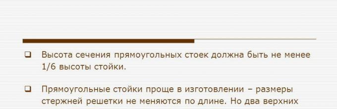
The height of the cross-section of rectangular racks should not be less than 1/6 of their length. The height of the maximum support section of triangular posts must be at least a quarter of their length. Rectangular racks are easier to manufacture, since the dimensions of the rods of their lattice do not vary in length, but they have two upper nodes that require fixing from the plane of the rack. Triangular racks are more economical in terms of wood consumption and have only one upper node, but are more labor-intensive to manufacture, since the dimensions of the lattice elements vary along their length.
The belts of the trellis racks can be double-stranded. Double-belted belts with short pads have greater rigidity in the direction from the planes of the rack, as well as gaps, which simplifies the attachment to them of a grid of bars or thick boards. One-strap belts are less labor-intensive to manufacture, but steel plates are required to attach rods to the grille. The lattice of these racks is usually diagonal-rack layout.
Nodal connections of lattice rods with double-strap belts are usually made by inserting their ends into the gaps between the bars of the belts and connecting them with bolts (Fig. 5.12.). The bolt placement conditions require a certain displacement of the rod axes from the center of the nodes. In this case, there is a slight eccentricity of the forces acting in the rods of the lattice, and a small bending moment in the racks, which can be neglected in the calculation.


Fig. 5.12. Lattice racks:
a - upper; b - supporting; c - intermediate; / - belt; 2 - bolts; 3-steel beam; 4 - anchors; 5 - steel corner; 6 - lattice rods; 7 - steel plates
The upper end of a rectangular rack is usually carried out using a horizontal beam of steel profiles, which is fastened to the belt of the rack with steel fasteners and bolts; the supporting structure of the coating rests on the middle of the length of this beam. The upper knot of the triangular stand is fastened by bolting the ends of the vertical and inclined stand belts. In this case, the support unit of the main supporting structure rests directly on the end of the vertical belt. Support units of these racks can also be solved with the help of steel plates anchored in the foundation concrete.
The calculation of lattice racks is based on the fact that they carry both vertical N and horizontal loads w and, from the point of view of calculation, are vertical cantilever trusses hinged to the foundation. Racks of a lower height than the recommended one should be calculated as squeezing-bending elements, rigidly attached to the foundations and having a free or pivotally fixed end.
These racks are affected by a vertical concentrated load from the own weight of the overlying structures and the weight of snow s and horizontal loads from pressure w + and wind suction, similar to loads on wooden racks of variable cross-section, which are conventionally concentrated in the nodes. From these loads, tensile or compressive forces arise in the pillars of the pillars, which are determined by general methods of structural mechanics, for example, by constructing the Maxwell – Cremon diagram. Maximum efforts occur in the belts and rods of the lattice adjacent to the support node. Efforts in the rods of the lattice arise only from the action of horizontal wind loads.
The belt of a rack works and pays off on durability and stability at compression in two planes. In the rack plane, its calculated length is taken equal to the distance between the nodes. From the rack plane, its calculated length is taken to be equal to the distance between its horizontal links. This takes into account the flexibility of connections
two-strap belt, as in the calculation of the two-strap composite rack. The strength of the belt is additionally checked at the maximum tensile strength from wind load.
The bars of the rack are calculated on the strength and stability under compression or tensile strength, taking into account their length and hinge mounting in the nodes. The top beam of a rectangular rack is calculated on the bend from the action of a concentrated load in the middle of its span.
Bolted connections of lattice elements with double-pillars are calculated for the forces in these elements as two-shear,
working symmetrically at an angle to the fibers of the wood belts. Bolts of steel plates of the lattice rods are calculated as two-shear, symmetrically working along the wood fibers. The bolt of fastening of these inserts to the single-strap belt is calculated on the difference in the forces in the adjacent panels of the belt. The bolted connection of the belts of the triangular stand in the upper knot works and is calculated as a single-cut asymmetrical one working at an angle to the wood fibers.
Support fixing the rack to the foundation is calculated on the action of the maximum tensile forces in the belts adjacent to the supports. When two-belted belts is determined by the required number
two-shear symmetrically working bolts fastening the gasket to the belt bars. The corner beam, which rests on the gasket, is calculated on a bend as a beam, which rests on the nuts of the anchor cords and is loaded with the reactive pressure of the gasket end. Single-strap belts can be fastened to the foundation with steel shoes, bolts and anchors.
Lecture 9 Racks.doc
Lecture number 9Wooden racks.
The loads perceived by the flat supporting structures of the coating (beams, covering arches, trusses) are transferred to the foundation through racks or columns.
In buildings with wooden bearing structures, it is advisable to use wooden pillars, although sometimes it is necessary to install reinforced concrete or metal columns.
Wooden racks are compressed or compressible-bending supporting structures, based on the foundations. They are used in the form of vertical rods that support the floor or overlap, in the form of struts of the strut systems, in the form of rigidly embedded racks of single-span or multi-span frames.
By design, they can be divided into glued racks and racks of solid elements.
Glued racks
Glulam and kleifanernye racks are elements of factory production.

^ Figure 1 - Glued racks
a) constant rectangular and square section;
b) variable rectangular section

^ Figure 2 - Glue racks
Glued racks can have a larger cross-section and a height of up to 8-10 m. For their manufacture, wood of 2 and 3 grades is used. Advantages of such racks consist in their industrialism, simplicity of transportation and installation.
Solid Elements Racks
Subdivided into the following types:
in the form of a single beam or log

^ Figure 3 - Racks of single logs and bars
These racks have a relatively small bearing capacity. Their height and cross-sectional size is limited by a range of timber.
In these racks usually used hinge bearing on the foundation.
Racks in the form of elements of a composite section recruited from two or more bars, boards or logs, connected by bolts or other compliant ties

^ Figure 4 - Composite Block Racks
a) solid; b) pass-through with gaskets; 1 - bars; 2 - bolts; 3 - gaskets

^ Figure 5 - Composite stand of boards
Racks of a composite section also have a height limited by the gauge, however, their carrying capacity can be significantly higher compared to racks of a single section.
The joints used for joining these racks (bolts, nails, pins) are pliable, which increases the flexibility of the racks and must be taken into account when calculating.
Wire racks
Apply most often as a squeezed-curved rack frames. They can be with parallel belts or with one inclined belt. A variation of the latter are triangular racks.

^ Figure 6 - Grid Racks
a) rectangular; b) triangular
Elements of lattice racks are connected in nodes on the bolts.

^ Figure 7 - Section of the lattice rack
a) a belt of two branches, a lattice of one; b) belt and lattice from one branch
If the lattice is made of one branch, and the belt is made of two (Fig. 7a), then the lattice is passed between the branches of the belts and fixed directly to the latter. If the belts and the grille are made single-branch (Fig. 7b), then the connection of the lattice elements with the belts is performed end-to-end, and the nodes are constructed with steel plates on the bolts.
Racks with parallel belts can be stepped. In this case, the supporting structures of the coating are supported on the higher outer belt, and the crane beams on the inner one.
Rack calculation
Calculation of efforts in the racks produced taking into account the loads applied to the rack.
^ Average racks
The middle racks of the building frame work and are calculated as centrally compressed elements to the effect of the greatest compressive force N on the own weight of all coating structures (G) and snow load and snow load (P sn).

^ Figure 8 - Medium Rack Load
The calculation of centrally compressed middle racks produce:
A) strength
Where is the calculated resistance of wood to compression along fibers;
The net area of the cross section of the element;
B) for sustainability
 ,
,
Where - the coefficient of buckling;
- the calculated cross-sectional area of the element;
The loads are collected from the floor area according to the plan per one average rack ().


^ Figure 9 - Cargo area middle and extreme columns
Extreme racks
The extreme stand is under the action of longitudinal with respect to the axis of the rack loads (G and P sn), which are assembled from square and cross, and X. In addition, a longitudinal force arises from the action of the wind.

^ Figure 10 - Extreme Rack Loads
G is the load from its own weight of the coating structures;
X - horizontal concentrated force applied at the point of contiguity of the bolt to the rack.
In the case of rigid mounting racks for single-span frame:

^ Figure 11 - Scheme of loads with rigid pinched racks in the foundation
Where - horizontal wind loads, respectively, from the wind to the left and to the right, attached to the rack at the place of contiguity of the crossbar.
![]()
![]()
Where - the height of the support section of the bolt or beam.
The influence of forces will be significant if the bolt on the support has a considerable height.
In the case of pivotally supporting the strut on the foundation for a single-span frame:

^ Figure 12 - Scheme of loads with hinged support racks on the foundation
For multi-span frame constructions, p 2 and w 2 on the left wind, and p 1 and w 2 on the right wind, will be equal to zero.
Extreme racks are calculated as compressible elements. The values of the longitudinal force N and the bending moment M are taken for such a combination of loads, at which the greatest compressive stresses occur.

1) 0.9 (G + P c + wind left)
2) 0.9 (G + P c + wind on the right)
For the rack, which is part of the frame, the maximum bending moment is taken as max from the calculated for the case of wind on the left M l and on the right M pr:
![]()
![]() ,
,
Where e is the eccentricity of the application of the longitudinal force N, which includes the most unfavorable combination of loads G, P c, P b - each with its own sign.
The eccentricity for racks with a constant section height is zero (е = 0), and for racks with a variable section height, it is taken as the difference between the geometric axis of the reference section and the axis of application of the longitudinal force.
The calculation is compressed - the curved extreme posts are made:
A) for strength:

B) on the stability of the flat shape of the bend in the absence of fixation or at the estimated length between the fixing points l p\u003e 70b 2 / n by the formula:

Geometric characteristics included in the formulas are calculated in the reference section. From the plane of the frame rack stand as a centrally compressed element.
^ Calculation of compressed and compressed-curved composite section is produced according to the above formulas, however, when calculating the coefficients φ and ξ, these formulas take into account an increase in the flexibility of the rack due to the flexibility of the links connecting the branches. This increased flexibility is referred to as λn reduced flexibility.
^ Calculation of lattice racks can be reduced to the calculation of farms. In this case, a uniformly distributed wind load is reduced to concentrated loads in the truss nodes. It is believed that the vertical forces G, P c, P b are perceived only by the rack belts.
Rack nodes
In the upper node, where the supporting structure of the coating rests on the rack, the rack experiences crushing along the fibers.

^ Figure 13 - Beam support unit on the rack
This node has the same solution for racks of various kinds.
Support node
For racks of solid elements and for glued racks, working in compression, the support unit is solved by simply placing the rack in a steel shoe, which is attached to the foundation with anchor bolts. Racks are attached to the shoe with bolts, the diameter and the number of which is determined by design considerations.
In squeezed-bending rigidly fixed racks, the knot can be implemented in the form of anchor tables attached to the rack with bolts.
The node perceives the longitudinal force N and the bending moment M.

^ Figure 14 - Knot Support Stand
The calculation of the support fastening is carried out with a combination of loads that cause the greatest tensile force N p in fasteners:

Where N and M is the longitudinal force and bending moment in the support section

Considering the additional bending moment from the longitudinal force,
E - shoulder forces N p and N e.
For the largest value of N p calculate the number of anchor bolts located on one side of the rack.
The force N is perceived by the collapse of the rack along the fibers.
Of the spacer planar through wooden structures the most widely used arch. Abroad systems of triangular shape composed of trusses with parallel belts made of solid or glued wood, as well as through trellised three-hinged frames, are of limited use abroad.
In the absence of a base for the production of glued wooden structures or other reasons that limit the possibilities of using glued arches, they are replaced by industrial enough through arched structures, the most common of which can be considered three-hinged arches from cobbled trusses.
The spread in such arches can be perceived by a metal tie or directly by foundations.
Fig. 1. A three-hinged arch span of 26 m from cobble farms
The spans, overlapped by such arches, are 20–40 m. The connections of the elements of the upper belts and the attachment of the grids in the trusses that make up the arch are carried out similarly to the nodes of cobble farms. The principal difference between trusses that form end-to-end arches and conventional trusses is that in the first case the lower truss belt can work in compression, while in the second the lower belt always works in tension. Due to the possibility of the appearance of compression forces in the lower belt, it is necessary to ensure its stability from the plane of the truss. It is provided by setting vertical ties in the plane of the uprights, the distance between the bonds is usually equal to twice the length of the lower belt panel.
A distinctive feature of the calculation of through arches is the need to determine the forces in the arch elements when the temporary load is located — not only on the entire span and half of it, but also on the quarter and three quarters of the span, since in these cases the maximum efforts are usually obtained in the arch grating elements.
Wire racks
Lattice racks are used to give the building lateral stability, as well as in the construction of end walls. Lattice racks consist of two branches, each of which is attached to the foundation with anchor bolts. Racks perceive vertical (weight of coating structures, roofing, etc.) and horizontal (from wind pressure and braking forces of a crane truck) loads.
Vkapitalnyh buildings and structures usually used lattice racks with parallel branches (Fig. 2, 6) or in the presence of a bridge crane with a stepped outline (Fig. 2, a) with their placement inside the building. Previously used trellis racks of triangular shape, which were located in the form of buttresses outside the building. The ratio of the distance between the centers of the branches at the base of the trellis rack to its height is recommended to be used within 1/5 - 1/8.

Fig. 2. Types of lattice racks:
a-with tap; b-no crane.
Each branch of the trellis rack can consist of one or two bars, made in the direction normal to the plane of the rack. For a single cross-section of the branch, a double lattice is used, covering the branches on both sides. Rack nodes are usually constructed with an eccentric attachment of lattice elements to the branches on the bolts. Racks are secured to foundations using metal anchors made of flat or round steel. The design of the lattice rack height of 9.24 m is shown in Fig. 3
Racks count on vertical and horizontal loads. When calculating the vertical load can be considered (neglecting the longitudinal deformations of the legs of the rack), the load applied to one branch is transmitted directly by this branch to the foundation, without causing an effort in the second branch of the stoics.

Fig.3. Cage stand 9.24 m high
Two racks, connected on top of the supporting structure of the roof covering, form the transverse frame of the building (see Fig. 2, b). In wooden frames, the connection of the bolts with the stand, as a rule, is assumed to be articulated, as a result of which the vertical load, bending the bolt, does not cause bending moments in the struts. Consequently, when calculating the horizontal load, the mutual connection of the struts with the bolt should be taken into account, deciding in the general case once a statically indefinable frame consisting of two fixed in the base of the struts connected on top of a hinged-attached bolt.
When determining the forces in the lattice elements of the rack from the action of horizontal loads, it is considered as a cantilever trusses, clamped in the foundation. Given the significant distance between the axes of the branches and usually their same cross-section, the calculation can be made using the formula
whereF nt - net area of one branch of the rack; N - force in the lower section of one branch of the rack og vertical load;N M = M / h 0 - compressive force from horizontal loads causing bending moment M y base rack.
The estimated length of the rack when determining its flexibility and coefficient is equal to twice the actual length (as for the console).
The malleability of the links connecting the lattice with the legs of the uprights is taken into account by introducing the coefficient reduced flexibility pr when calculating the coefficient, considering the flexibility of an individual branch 1 = 0. The number of links slices n c (bolts, nails) by one m of the length of the rack is determined by dividing the number of cuts in the node by the length of the rack panel.
The stability of a separate branch of the rack is checked according to the formula
where i - buckling coefficient determined by the estimated length l 1 , equal to the distance between the nodes of the rack;F br - the gross area of the branch;W br - moment of gross resistance of the branch section; M D = M / - bending moment in the rack, determined by the deformed scheme; M - bending moment at the base of the rack.
The calculation of the elements of the rack from the plane of the frame produced without taking into account the bending moment M, separately for each branch of the rack at a calculated length equal to the distance between the spatial connections, securing the branches. If the branch section is composite, then the calculation is carried out as for a composite centrally compressed rod. Efforts in the lattice elements are defined as in the farm, followed by dividing by the coefficient . Anchors are calculated on the maximum tensile force in the legs of the rack under the action of a constant vertical minimum possible and maximum horizontal loads.
Ministry of Transport of the Russian Federation Federal Agency of Railway Transport
Federal State Budgetary Educational Institution of Higher Professional Education
"Far Eastern State University of Communications"
Department "Building structures, buildings and facilities"
V.A. Tanayev
WOODEN GRID RACK
2nd edition, amended and corrected
as a teaching tool
Khabarovsk Publishing House DVGUPS
UDC 624.011.1 (075.8)
BBK N 55 YA73
Reviewers:
Department of Building Structures of Pacific State University (Head of the Department is Candidate of Technical Sciences,
associate Professor N. E. Medvedev)
Chief Engineer of the Khabarovsk Design and Survey Institute “Dalzheldorproject” - a branch of the OJSC “Roszheldorproject”
V.I. Eroshenko
Tanayev, V.A.
T 180 Wooden lattice racks: studies. manual / V.A. Tanayev. - 2nd ed., Ext. and rev. - Khabarovsk: DVGUPS Publishing House, 2012. - 74 p. : il.
The types of structures and design principles of wooden lattice racks in the frame of a one-story industrial building are considered. The focus is on the layout of the framework, the collection of load and the calculation of structures. An example of the design of wooden structures of the transverse frame, including the floor, truss, stepped rack, is given.
Designed for students of all forms of education, performing a course project in the discipline "Constructions of wood and plastics."
UDC 624.011.1 (075.8)
BBK N 55 I 73
© FESTU, 2006, 2012
PDF created with pdfFactory Pro trial version www.pdffactory.com
INTRODUCTION
Among other types of composite racks, wooden lattice racks have the greatest load carrying capacity and can be used as supporting structures in the span of buildings and bridge cranes with a lifting capacity of up to 10 tons.
Wooden trellis racks refer to constructions of construction, which are effective where wood is the local building material.
In the Far East, in many areas, wood is a local building material, and construction sites are located away from industrial centers, where transportation of factory products is difficult.
Therefore, the possibility of construction of building structures made of wood here is an advantage compared with the designs of factory made of reinforced concrete, steel or laminated wood. This is especially evident in the construction of temporary and auxiliary production facilities.
This implies the need to study in the course "Designs of wood and plastics" features of the layout of composite lattice racks and their design schemes, design techniques.
The manual consists of two parts.
AT part 1 describes the construction of lattice racks, the method of their calculation with the collection of loads and the definition of design combinations of efforts. Considered in detail the design scheme of the stepped lattice rack for its nadkranovoy and crane parts and methods for the selection of cross-sections of the rack.
AT part 2 considers a numerical example of designing structures of a single-storey industrial building with bridge cranes, including the layout of the transverse frame, calculations of supporting structures of the coating in the form of flooring and roofing, roof framing with selection of belt sections and grille, development of truss sections, and also the calculation of a wooden lattice rack transverse frame and elements of its attachment to the foundation.
When calculating the truss truss is used PC.
All calculations are performed in compliance with the international system of units of SI.
AT the annex to the training manual contains drawings with specifications of the extreme rack, as well as two options for an intermediate trellis rack with through and swinging tent branches, a range of sawn timber and the geometric characteristics of the cross-sections of round timber.
Having studied the textbook, the student has the opportunity to independently master the design of wooden structures, using the literature specified in the attached bibliography.
PDF created with pdfFactory Pro trial version www.pdffactory.com
PART 1 DESIGN OF GRIDED RACKS
1. STRUCTURED STACK STRUCTURES
Lattice racks are used in frames to ensure their lateral stability and rigidity, as well as in the end walls of buildings
In capital buildings, the racks are located inside the building. In the form of buttresses of a triangular outline, lattice racks are installed outside the building.
Rack branches consist of one or two edged logs or bars and are interconnected in bolted bars. The angle of inclination of the grid to the horizon is taken within 45 ... .55 °. Racks perceive the vertical load from the coating, snow and cranes, as well as horizontal - wind and braking cranes trucks. At the top of the rack are pivotally connected to the trusses or covering beams. The trusses (beams) of the coating are installed on the supporting beams and fixed from the sides with the plates (Fig. 2, a), or with the corners on the bolts (Fig. 3). Racks are rigidly fixed to the foundations with the help of a structure consisting of anchor bolts, crossbars and gaskets (Fig. 2, b).
The lateral design of the frame with lattice racks is a frame with rigid knots at the bottom and a hinged fastening to the bolt. In buildings with bridge cranes, the lower part of the lattice racks is constructed of two (Fig. 4, a, b, c) or three branches (Fig. 4, d) and a grid connecting the outermost branches of the rack.
The top of the rack consists of one branch, which is a continuation of the lower branch and together with it forms a through tent branch (Fig. 4, a, c, d).
In the intermediate posts, the overcrane part can also be in the form of an independent swinging stand, which rests on the traverse of the lattice part (Fig. 4, b and adj. 4).
In terms of wood consumption, racks with swinging branches are 20% more economical than racks with through tent branches. However, they are somewhat more complicated in terms of installation.
It is advisable to use the upper branches in the form of swinging racks when their height is 1.5 ... 2 times the height of the upper branches of the outermost racks (for example, with a slope of a leaning to the middle rack of the roof equal to 1: 5). In these cases, the transverse rigidity of the frame does not depend much on the pattern of fastening the upper arm of the intermediate stand, and therefore both structural schemes of the intermediate stand can be used.
PDF created with pdfFactory Pro trial version www.pdffactory.com
Fig. 1. Lattice racks in the composition of the transverse frames
PDF created with pdfFactory Pro trial version www.pdffactory.com

Fig. 2. The structure of the stand in buildings without cranes with the covering of the beam of the beam on one branch of the rack: a - general view; b - attachment to the foundation; 1 - glulam beam; 2 - supporting beam; 3 - cover plate; 4 - traverse; 5 - anchor bolts; 6 - waterproofing
PDF created with pdfFactory Pro trial version www.pdffactory.com

Fig. 3. The structure of the stand in buildings without cranes with the support of the truss covering two branches of the rack: 1 — truss; 2 — longitudinal (supporting) beam; 3 — traverse; 4 — anchor bolts; 5 — laying; 6 — waterproofing
PDF created with pdfFactory Pro trial version www.pdffactory.com

com.pdffactory.www version trial pro pdfFactory with |
Fig. 4. Structures in buildings with cranes: a, b - extreme frame pillars, c, d - intermediate frame pillars, 1 - hip branch, 2 - crane branch, 3 - swing stand, 4 - through hip branch, 5 - traverse
With the same height nadkranovyh branches of extreme and intermediate racks transverse rigidity of the frame when working on wind load depends largely on the stiffness of the upper branches of the middle columns. In this case, the use of a swinging rack is impractical.
The dimensions of the cross-section of the lattice racks are determined by the ratio between the span of the building and the span of the bridge crane, as well as the stiffness of the transverse frame. From the stiffness condition, it is recommended to take the ratio of width h 0 to the height of the crane branch, equal to 1/5 ... .1 / 8 for racks with parallel branches and 1/4 ... 1/6 - for buttresses of a triangular outline. Crane branches racks are usually located along the axis of the crane tracks.
The branches of the trellis racks are constructed of two logs with a diameter of 200 ... 240 mm, edged on two or four sides and spaced apart by the thickness of the grid (100 ... 120 mm). Lattice elements are constructed from 150 mm wide bars.
The grille is connected to the branches on bolts with a diameter of 20 ... 25 mm. The distance between the bolts along the length of the branch is recommended to assign no more than 7 thicknesses of logs. In this case, when calculating the flexibility of the branch is taken to be equal to λ y 0 = 0. Lattices of a lattice do not fasten -
sya to the tent branch (Fig. 4, d). The vertical load from the coating is transferred by this branch directly to the foundation.
The joints of the outer branches of the outer posts are located in any panel of the lattice part, except the top. In the through tent branch of the intermediate posts in order to more rigidly pinch the branch, the joint should be located within the lower half of the lattice part of the rack.
The longitudinal stiffness of the building frame is ensured by the installation of vertical cross ties in the form of bracings made of round steel with wooden struts between the outermost columns along the length of the building.
2. BASIC PROVISIONS FOR CALCULATING RACK-MOUNTED RACKS
When determining stresses in a rack from a vertical load, it can be considered (neglecting the longitudinal deformations of the branches of the rack) that the load applied to one branch is transmitted directly by this branch to the foundation without causing (through the grid) the forces in the second branch of the rack.
In the approximate calculation of stepped lattice racks, it is assumed that horizontal loads from wind and braking applied to the lower (lattice) part of the rack do not cause any effort in the upper
PDF created with pdfFactory Pro trial version www.pdffactory.com

night stand. Therefore, it is customary to rely on the upper part of the uprights with the crossbar as wind loads as an independent frame with fixed pillars of constant cross section (Fig. 5, b).
Fig. 5. Design schemes of stepped lattice racks: a is the initial scheme of the transverse frame, b is the design scheme of the above-crane part of the frame for the action of wind and braking, and c is the design scheme of crane crane racks
When determining the forces in the lower lattice part of the rack, it is considered as a cantilever trussed in the foundation and loaded with forces from the top of the racks, as well as directly applied to it by loads (fig. 5, c).
When determining the crane loads acting on the lattice part, we believe that the bars of the crane branch, connected together by bolts with gaskets, work together. Therefore, the vertical pressure D max and the horizontal braking force T max are assumed to be applied to the center of gravity of the branch section.
PDF created with pdfFactory Pro trial version www.pdffactory.com